


 In this post we will configure our first NSX-T site, the imaginatively named, Site A.
This is where the “rubber meets the road”. In this post not only will we deploy an NSX-T manager appliance, we will hook it into vSphere and complete the configuration required to prepare the site so that it can be ‘paired’ with Site B in preparation to run stretched layer 2 networks across both sites Site A and Site B.
This post is part 2 of a multipart series. Find the other parts here:
- Part 1: Lab Setup and Overview
- Part 2: This Part: Site A Build
- Part 3: Automated Site B Build
- Part 4: Multi Site Federation
- Part 5: Remote Tunnel Endpoints
- Part 6: Federated Tier-0 Gateway
- Part 7: Federated Tier-1 Gateways
- Part 8: Egress Traffic and MEDdling with BGP
As a reminder, in this series we will be building the following lab:
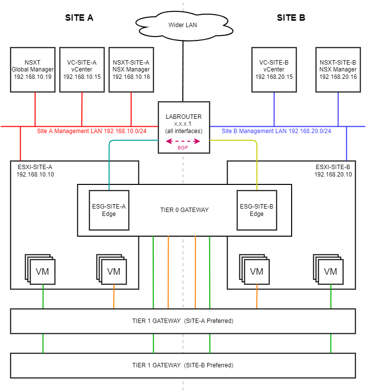 (Click image to zoom in)
Overview
Site A Build
OVA Deployment + Licencing
See NSX-T Download to get your very own copy of NSX-T and an evaluation licence too!
For brevity I’m not going to cover the deployment of the NSX-T manager OVA here, suffice to say that the following options should be selected when deploying the NSX-T OVA:
- VM Name = NSXT-SITE-A
- VM Size = Small
- Hostname = nsxt-site-a
- Role = NSX Manager
- IP = 192.168.10.16
- Mask = 255.255.255.0
- Gateway / DNS / NTP = 192.168.10.1
- Enable SSH + SSH root login = ticked
Site A Transport Zones
See Transport Zone for further details.
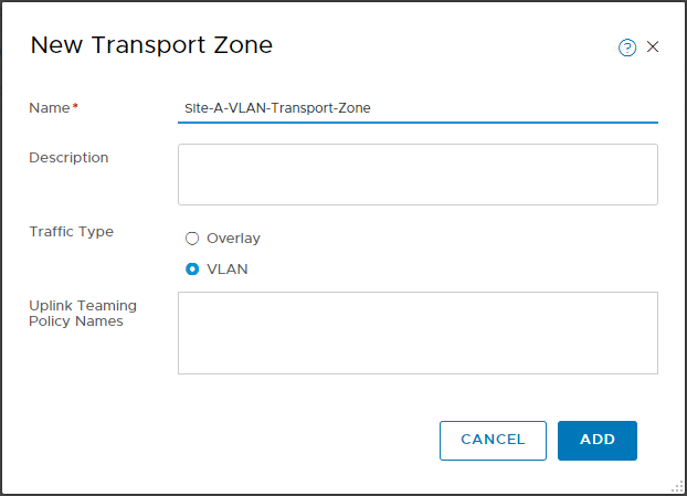
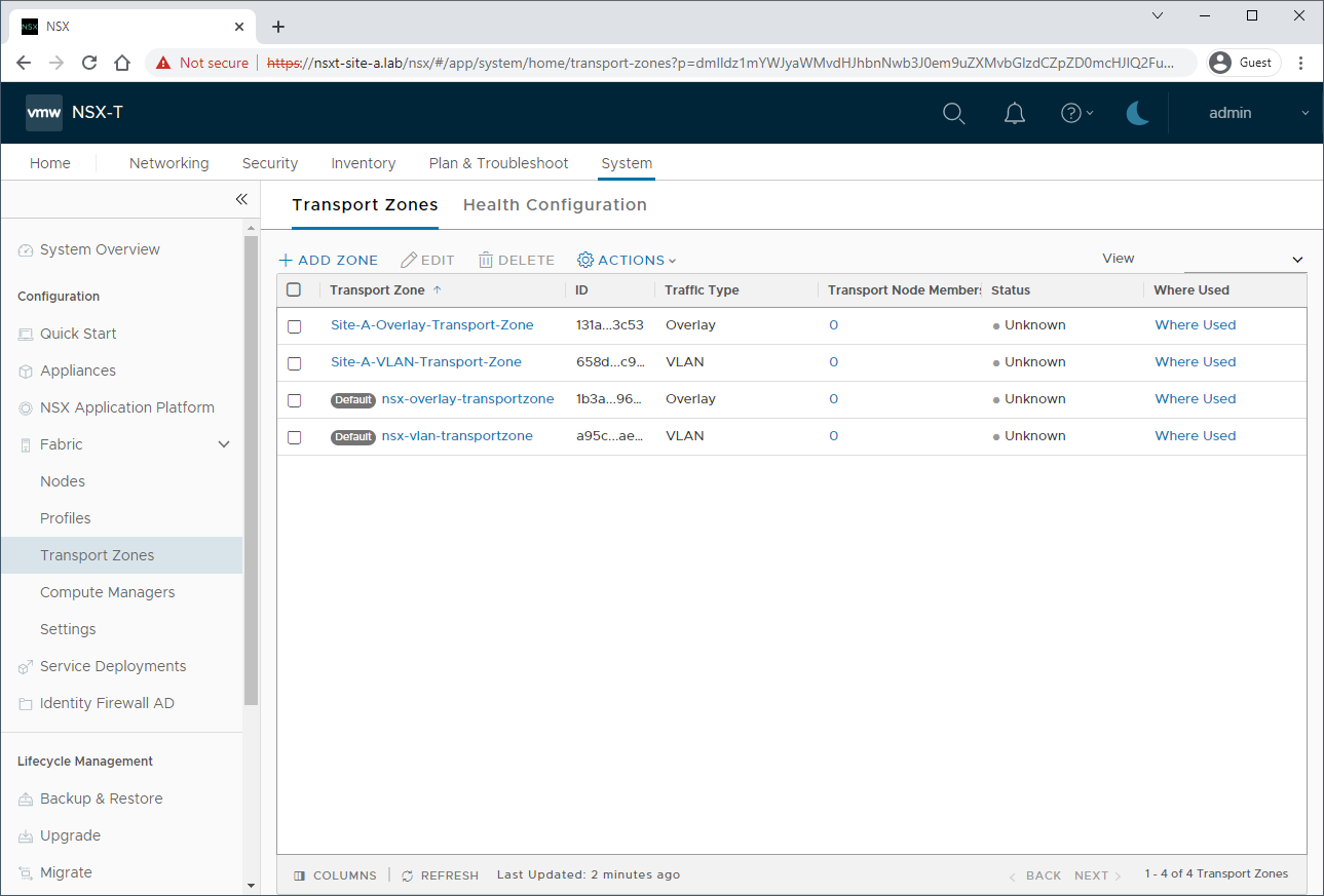
After logging into NSX-T manager, select System > Fabric > Transport Zones > Add Zone and create two zones, one overlay zone named Site-A-Overlay-Transport-Zone:

And one VLAN transport zone named Site-A-VLAN-Transport-Zone:
When complete you should have the following:
Site A Host and Edge Uplink Profiles
Next, lets create our uplink profiles. See Uplink Profile for further details.
Select System > Fabric > Profiles > Uplink Profiles > Add Profile.
Name the profile Site-A-Host-Uplink-Profile and scroll down to Teamings. Leave the teaming policy as Failover Order and name the Active Uplinks Uplink-1,Uplink-2. As per Site A VLANs and Subnets, set the Transport VLAN to 11. As we are using a VDS, there is no need to set an MTU:

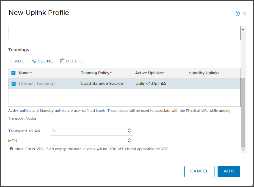
Select Add Profile again and lets create a profile named Site-A-Edge-Uplink-Profile.
Scroll down to Teamings. Set the teaming policy to Load Balance Source and name the Active Uplinks Uplink-1,Uplink-2. As per Site A VLANs and Subnets, set the Transport VLAN to 11:
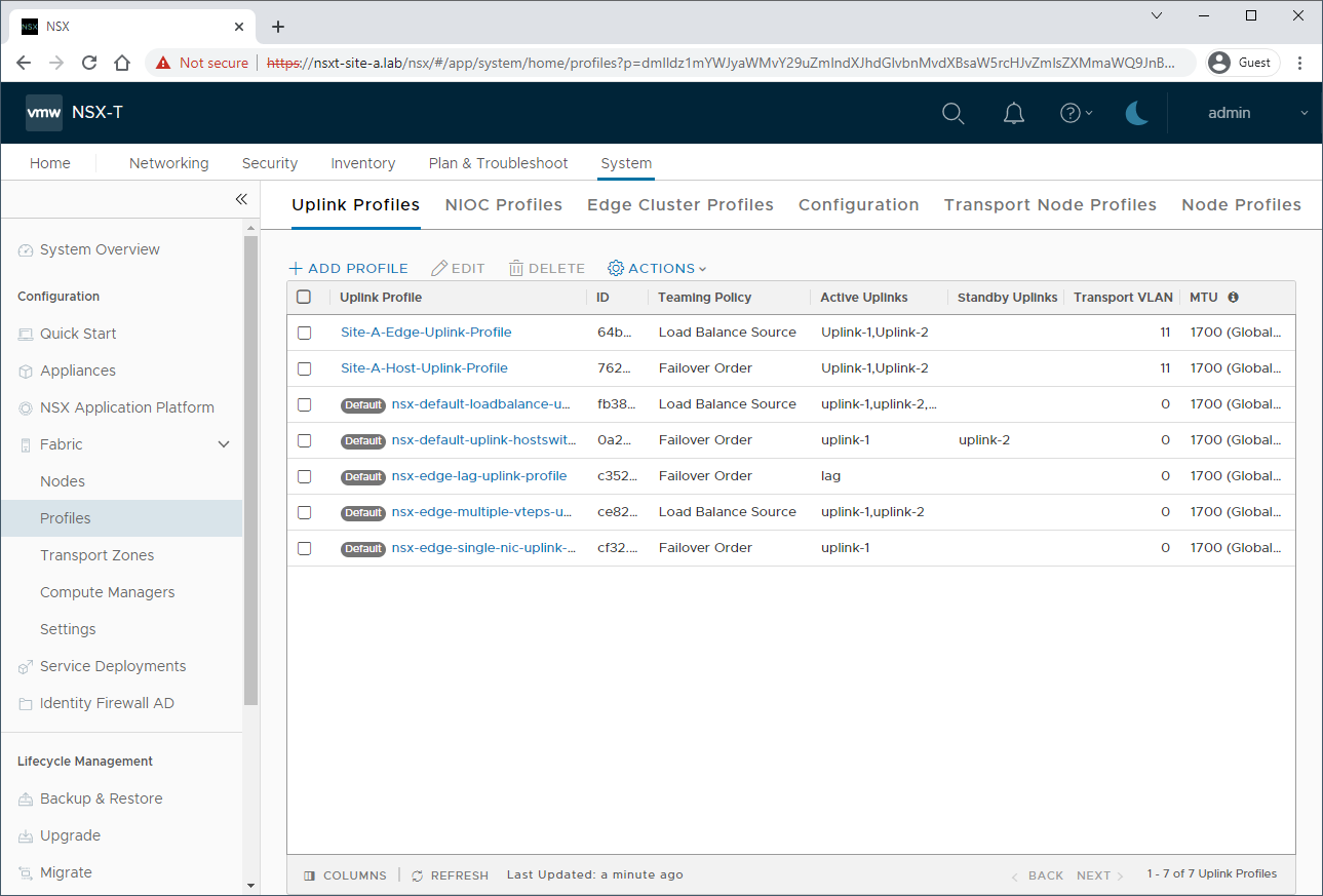
When complete you should have the following:
Site A TEP Pool
Next, lets create our Tunnel End Point (TEP) pool. As per NSX-T Edge TEP networking options (83743) we will create a single TEP pool for use by both our edges and hosts.
A Tunnel End Point is the IP address of a transport node (Edge node or Host) used for Geneve encapsulation within a location.
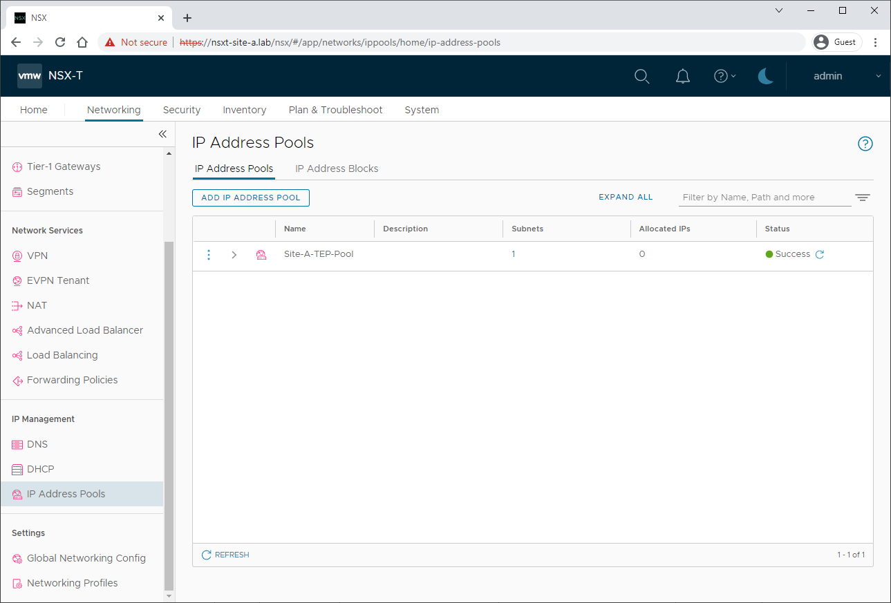
Select System > Networking > IP Address Pools > Add IP Address Pool.
Name the Pool Site-A-TEP-Pool, click Set > Add Subnet > IP Ranges.
As per Site A IP Allocation, set the IP range to 192.168.11.2-192.168.11.254, the CIDR to 192.168.11.0/24, the Gateway IP to 192.168.11.1 and click Add:
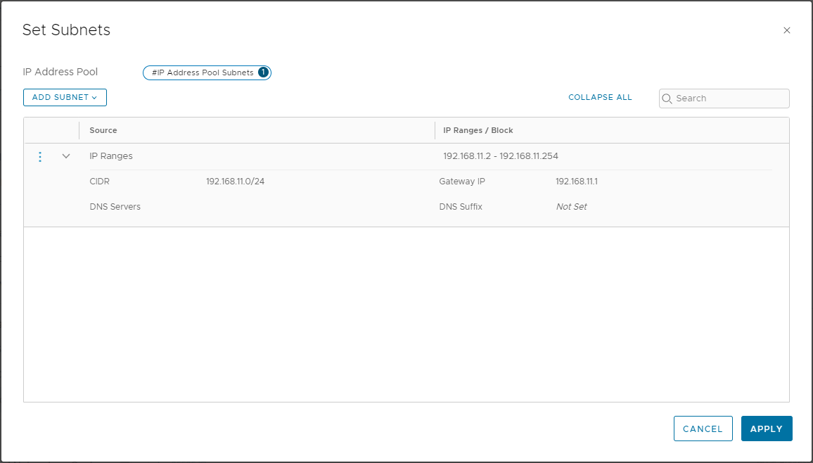
Click Apply and Save. When complete you should have the following:
Attach vCenter
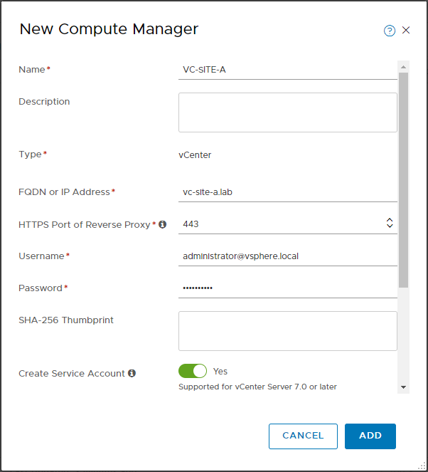
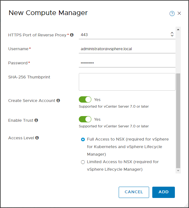
Next, lets attach our Site A vCenter.
Select System > Compute Managers > Add Compute Manager, complete the wizard, click Add and accept the thumbprint when prompted:
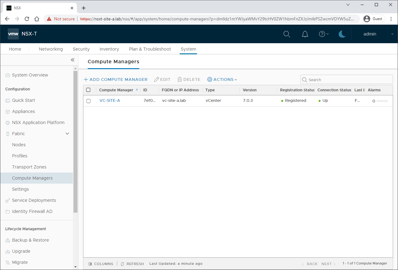
When complete you should have the following:
Create Transport Node Profile
Next, lets create our Transport Node profile. See Transport Node Profile for further details.
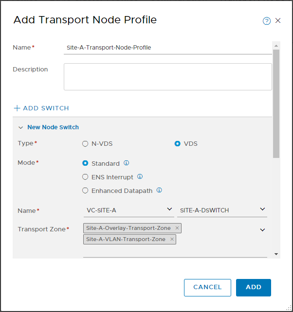
Select System > Fabric > Profiles > Transport Node Profiles > Add Profile.
Name the profile Site-A-Transport-Node-Profile.
Select VDS and Standard.
Select VC-SITE-A and SITE-A-DSWITCH.
Add both Site-A-Overlay-Transport-Zone and Site-A-VLAN-Transport-Zone transport zones
Select Site-A-Host-Uplink-Profile
Select Use IP Pool and Site-A-TEP-Pool
Finally, select Uplink1 and Uplink 2
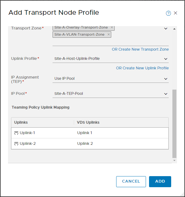
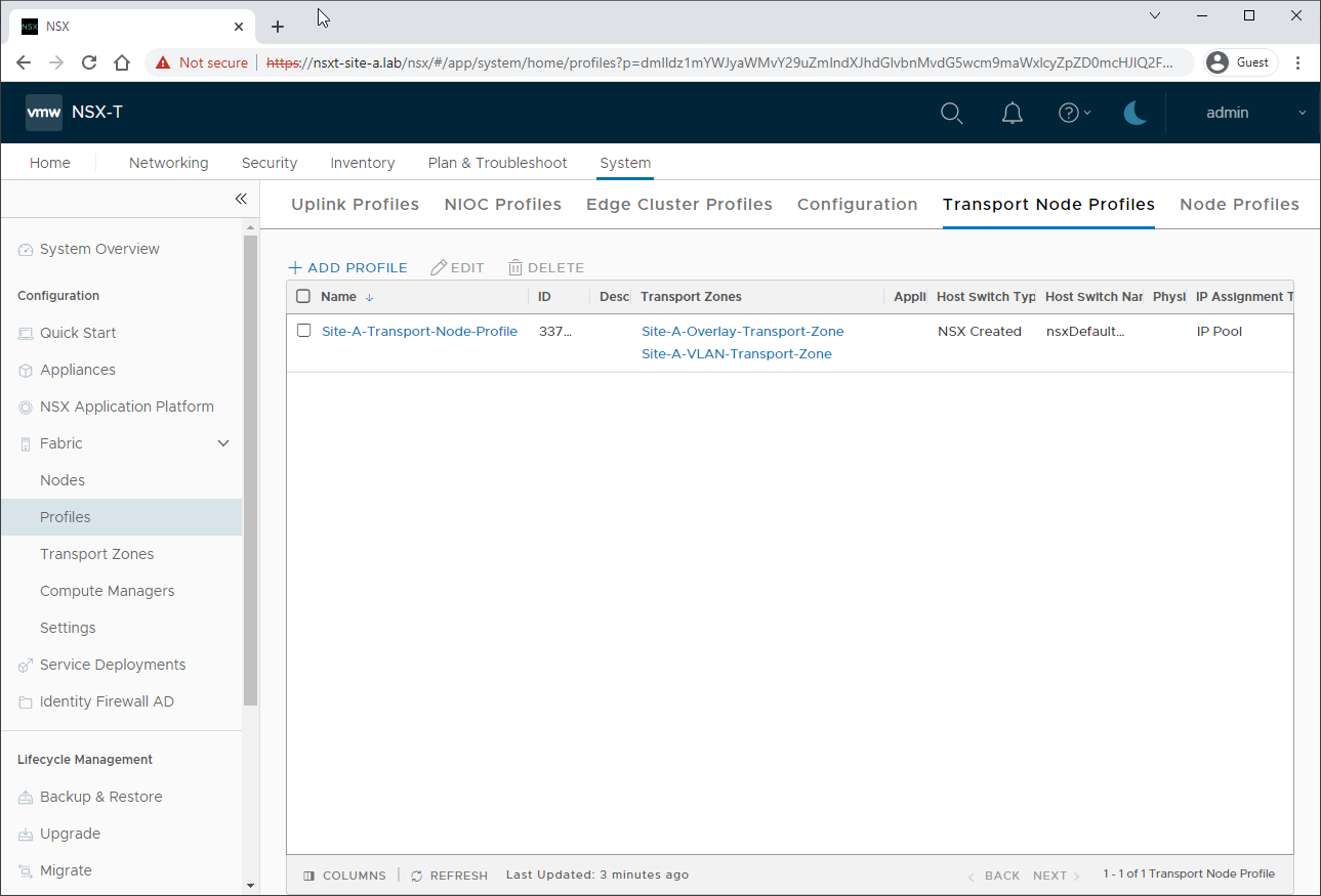
When complete you should have the following:
Prepare Host
Next we need to apply our configuration to our compute node cluster.
Select System > Fabric > Nodes. In the drop down, select VC-SITE-A.
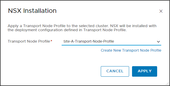
Next select SITE-A-CLUSTER and Configure NSX.
Select Site-A-Transport-Node-Profile and click Apply:
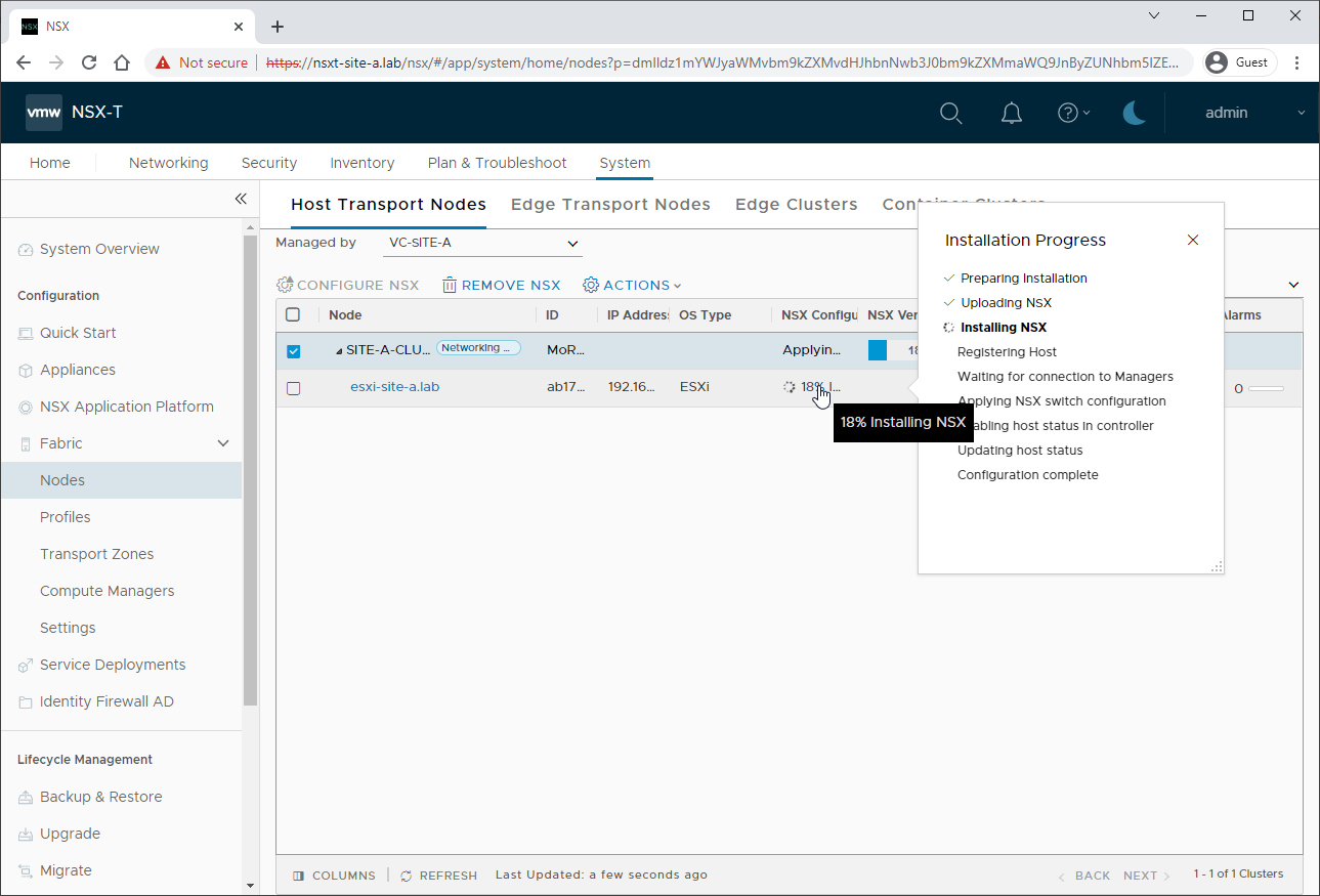
Allow time for the host preparation to complete:
Check TEP Connectivity
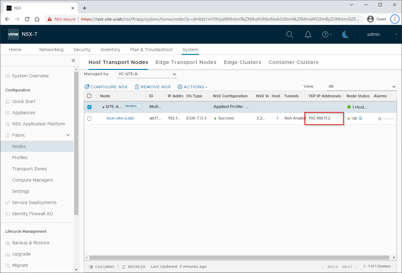
Make a note of the Host’s assigned TEP IP address:
Open a SSH connect to the lab router and lets see if we can ping the Host TEP IP over VLAN 11:
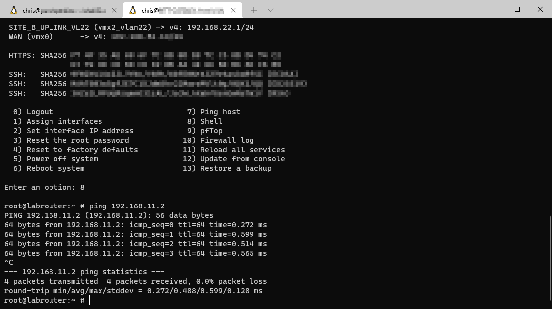
Yep, looks good.
Create Trunk VLAN Segment
So that we may also put our Edge TEPs onto VLAN 11, we need to create a VLAN Trunk segment within NSX-T.
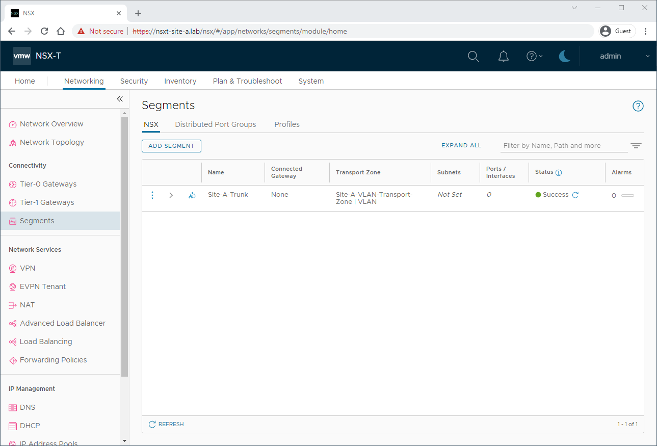
Select System > Networking > Segments > Add Segment.
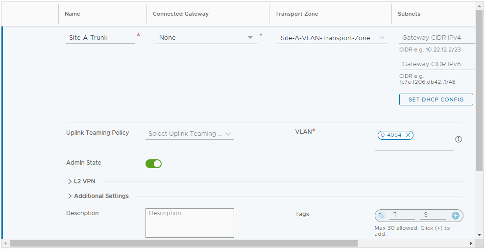
Name the Segment Site-A-Trunk, Connected Gateway to None, Transport Zone to Site-A-VLAN-Transport-Zone and enter VLAN of 0-4094:
Click Save when complete and No to continuing configuration. When complete:
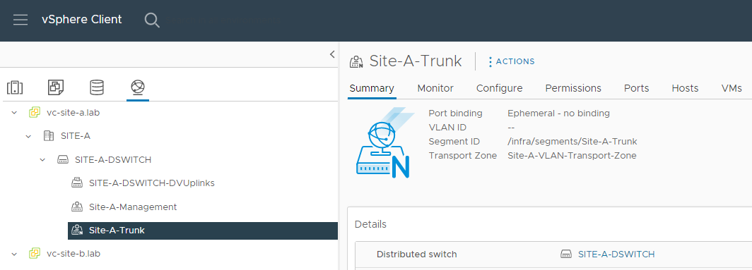
The trunk segment should be visible in vCenter:
Create Site A Edge Node
As this edge node is purely for our lab, lets size it accordingly.
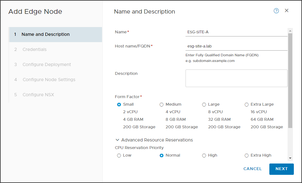
Select System > Fabric > Nodes > Edge Transport Nodes > Add Edge Node.
Name the node ESG-SITE-A, FQDN to esg-site-a.lab. Set Form Factor to Small
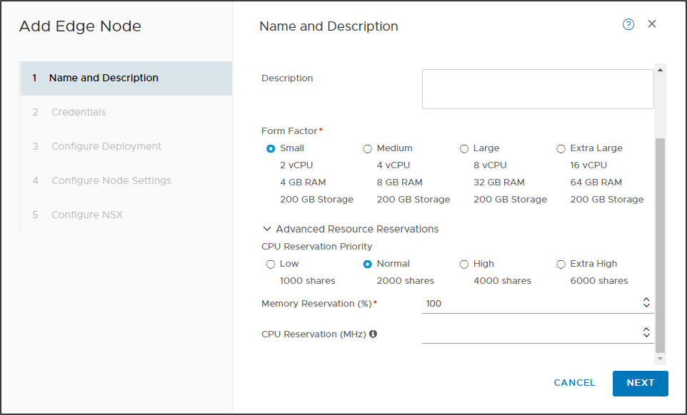
Set CPU Reservation priority to Normal and Memory Reservation to 0:
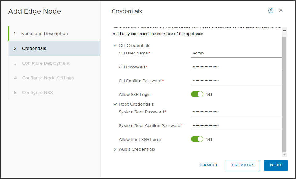
Click Next. Complete credentials and enable SSH logins:
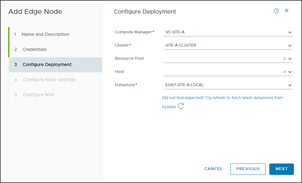
Click Next. Select vCenter, Cluster and Datastore:
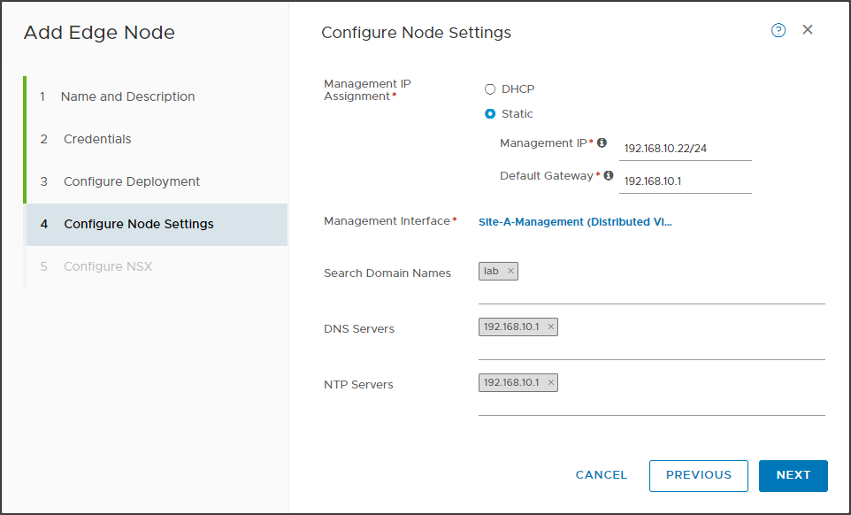
Click Next. As per Site A IP Allocation, assign static IP of 192.168.10.22/24 and gateway of 192.168.10.1.
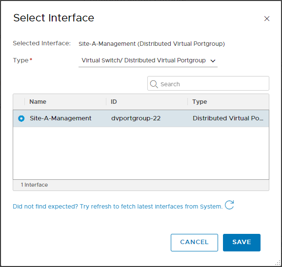
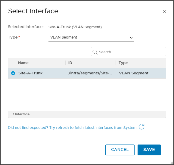
Click Select Interface and select Site-A-Management:
Click Save and set DNS search domain to lab, DNS and NTP servers to 192.168.10.1:
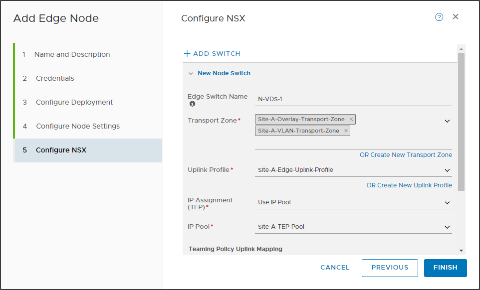
Click Next. Name the switch N-VDS-1.
Add both Site-A-Overlay-Transport-Zone and Site-A-VLAN-Transport-Zone transport zones.
Set Uplink profile to Site-A-Edge-Uplink-Profile.
Select Use IP Pool and Site-A-TEP-Pool.
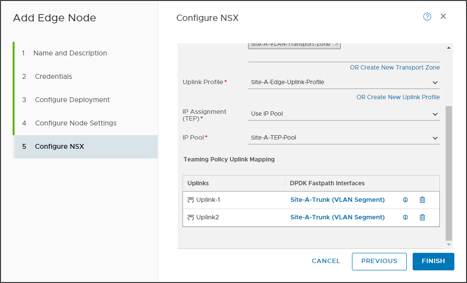
Finally, Set Uplink-1 and Uplink-2 to Type VLAN Segment and Site-A-Trunk:
Click Save and confirm configuration matches below:
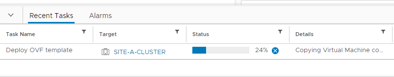
Finally, click Finish.
Allow time (circa 5 to 10 minutes) for the edge node to be deployed and configured:
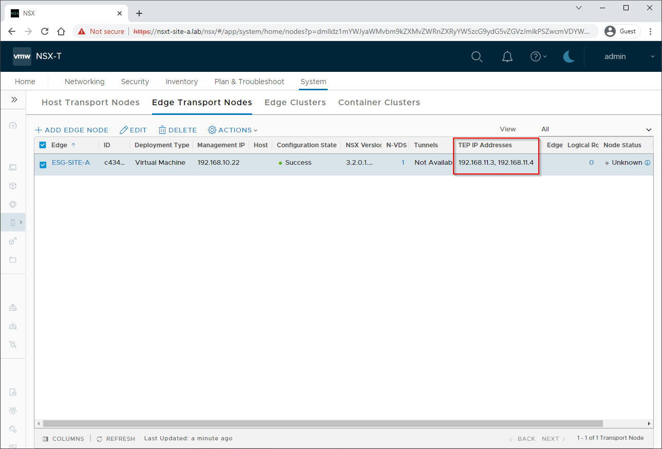
Upon successful completion of initial configuration, the edge should have been deployed, configured and received two TEP IP addresses:
Lets open an SSH connect to the lab router and lets see if we can ping the Edge TEP IPs over VLAN 11:
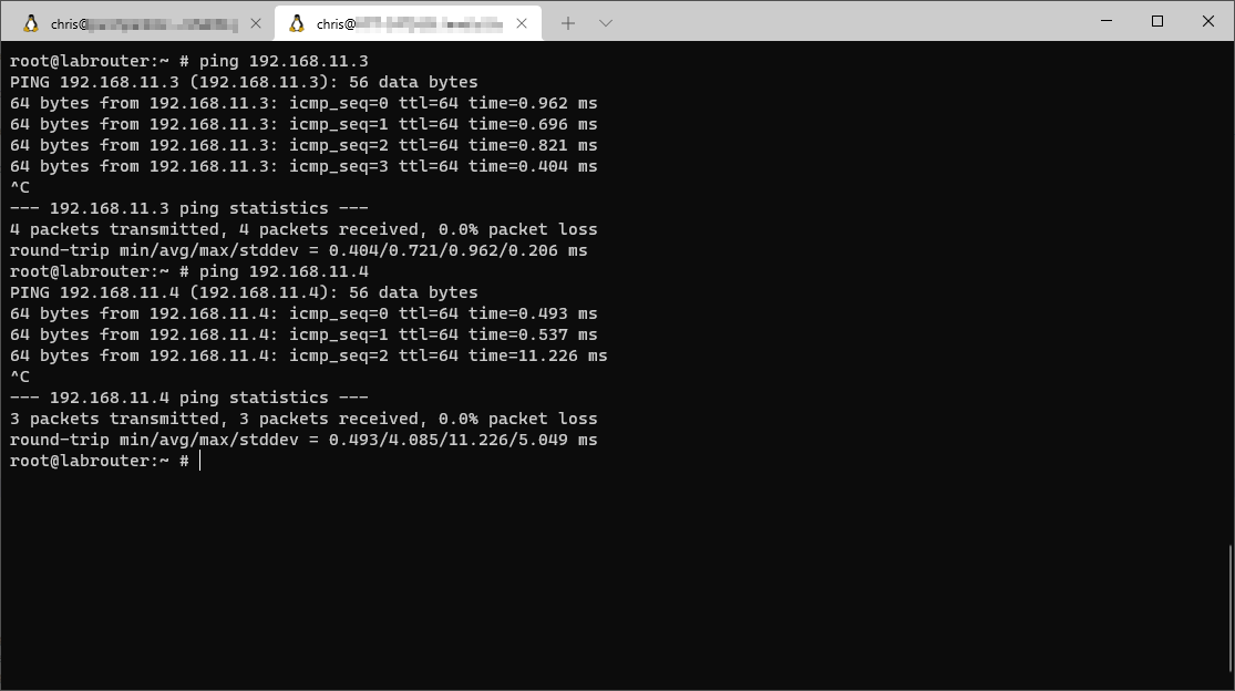
Yep, they look good.
Create Site A Edge Cluster
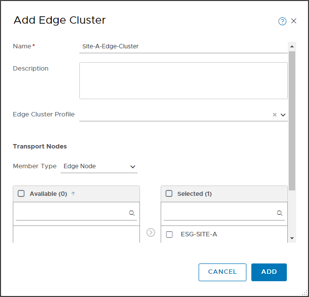
Select System > Fabric > Nodes > Edge Clusters > Add Edge Cluster.
Name the cluster Site-A-Edge-Cluster and use the arrow to move ESG-SITE-A from the Available box to the Selected box:
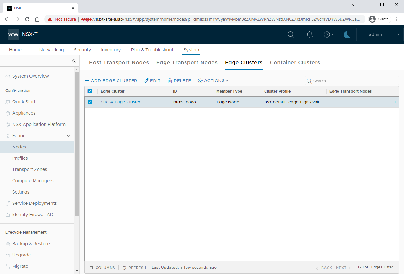
Click Add. Upon completion the following should be seen:
Conclusion and Wrap Up
We made it!
In this post we deployed NSX-T into and configured our first site (the imaginatively named) Site A ready to receive NSX-T federation, and some overlay configuration.
Whilst we don’t yet have all the configuration in place in Site A to produce a half a working cross site NSX-T federated setup, we are well on the way.
We still have to create our Global Tier 0 and Tier 1 Logical routers before we can hook any VMs into our NSX-T build. We will look at that in a later part of this series.
This was part 2 of a multipart series. Find the other parts here:
- Part 1: Lab Setup and Overview
- Part 2: This Part: Site A build
- Part 3: Automated Site B Build
- Part 4: Multi Site Federation
- Part 5: Remote Tunnel Endpoints
- Part 6: Federated Tier-0 Gateway
- Part 7: Federated Tier-1 Gateways
- Part 8: Egress Traffic and MEDdling with BGP
Look out for future parts coming soon!
-Chris