


 Over the last seven (!!) posts, we built our dual site NSX-T lab. We even simulated a site failure.
Nice.
If you missed any of the previous parts of this series, find the them here:
- Part 1: Lab Setup and Overview
- Part 2: Site A Build
- Part 3: Automated Site B Build
- Part 4: NSX-T Site Federation
- Part 5: Remote Tunnel Endpoints
- Part 6: Federated Tier-0 Gateway
- Part 7: Federated Tier-1 Gateways
- Part 8: This Part: Egress Traffic and MEDdling with BGP
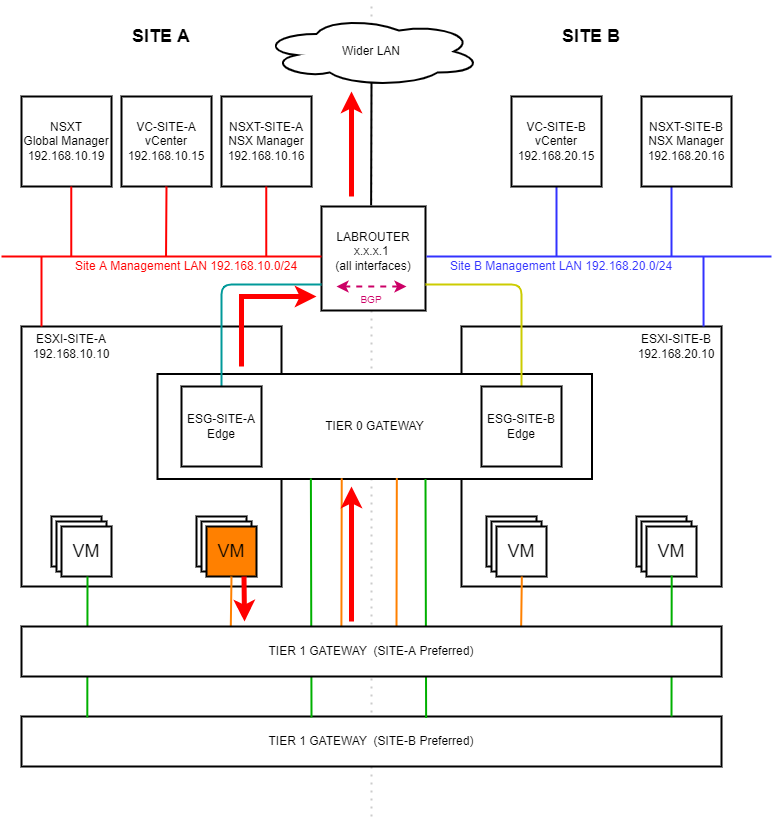
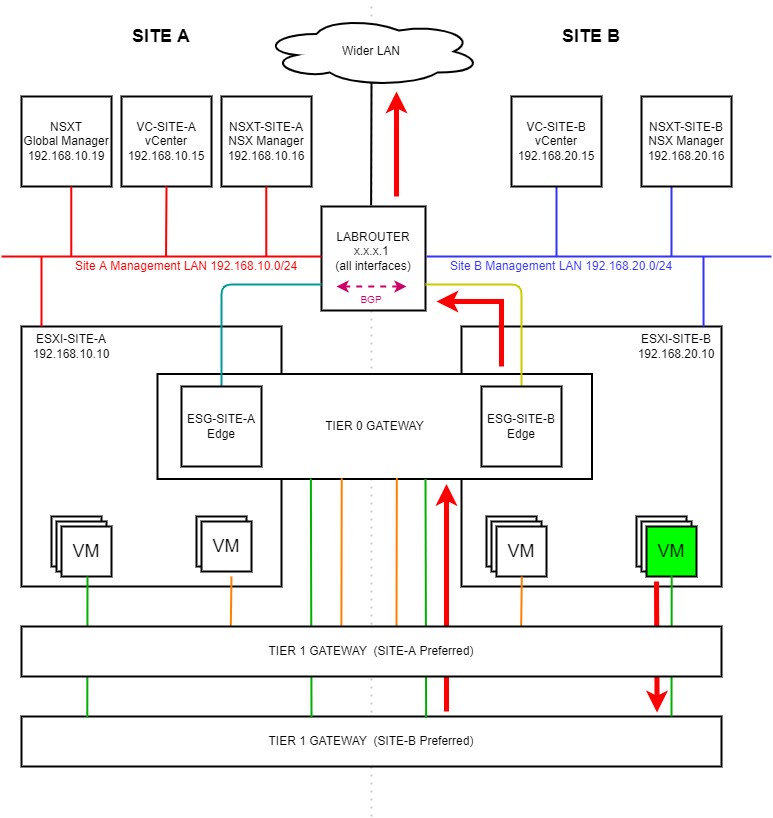
As a reminder, in this series we have built the following lab:
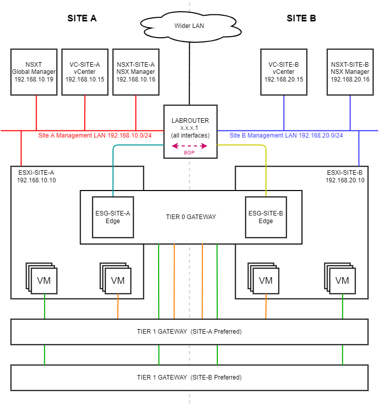 (Click image to zoom in)
With all of that done, we were left with two items of business to address:
- BGP
 - As discussed at the time in part 7, BGP is… entertaining.
 - Egress traffic - Is traffic flowing out of the environment as we expect?
Let’s address both of these items of business in this post.
Overview
BGP
The Issue
As we saw in this section of part 7:
As alluded to above, keen readers will spot that traffic is ingressing via one site at a time. That is traffic bound for Site-B-APP (192.168.50.1) is, under normal circumstances entering the environment via Site A.
Let’s fix that.
The Fix: BGP MED
The BGP Multi Exit Discriminator (MED) attribute, often referred to as BGP MED, provides a means to convey to a neighbouring Autonomous System (AS) a preferred entry point into the local AS. Learn more about BGP MED.
The BGP MED attribute allows us to set a preferred path. The path with the lowest MED value is the preferred path.
With that in mind, let’s look at our NSX-T Tier-0 to LABROUTER set up. Let’s also plumb in some MED values for our Site-A-APP (192.168.40.0/24) and our Site-B-APP (192.168.50.0/24) overlay segments:
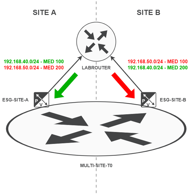
As you can see, our Site-A-APP (192.168.40.0/24) segment has a MED of 100 on Site A where as it has a MED of 200 on Site B. Conversely, our Site-B-APP (192.168.50.0/24) segment has a MED of 200 on Site A where as it has a MED of 100 on Site B.
This means that Site-A-APP traffic is preferred on Site A and Site-B-APP traffic is preferred on Site B. Should a site failure occur, BGP will redirect our traffic to the site with the MED 200 value. Exactly what we want!
Configuring BGP MED in NSX-T
To configure BGP MED in NSX-T we need to configure three items:
- IP Prefix Lists - These will be used to hold our collection of networks at each site
- Route Maps - These will be used to apply the MED values to each IP Prefix List at each site
- Route Filter - These will be used to apply our Route Maps to our BGP traffic
IP Prefix Lists
We will need two IP Prefix lists; one for Site A and one for Site B. Lets create them now.
Logon to the global NSX-T manager and select Networking > Tier-0 Gateways > Multi-Site-T0. Click the three dots next to the Multi-Site-T0 gateway and select Edit.
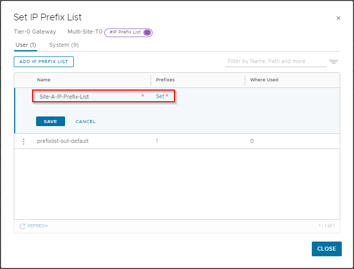
Scroll down and expand Routing and click the number next to IP Prefix Lists. In the Set IP Prefix List window, select Add IP Prefix List.
Name the list Site-A-IP-Prefix-List and click Set:
Click Add Prefix, enter 192.168.40.0/24 as a network and set the action to Permit:
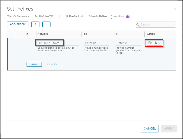
Click Add, Apply and Save to save the list.
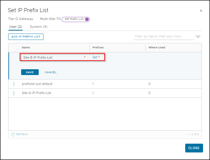
Let’s create our Site B IP Prefix List. In the Set IP Prefix List window, select Add IP Prefix List.
Name the list Site-B-IP-Prefix-List and click Set:
Click Add Prefix, enter 192.168.50.0/24 as a network and set the action to Permit:
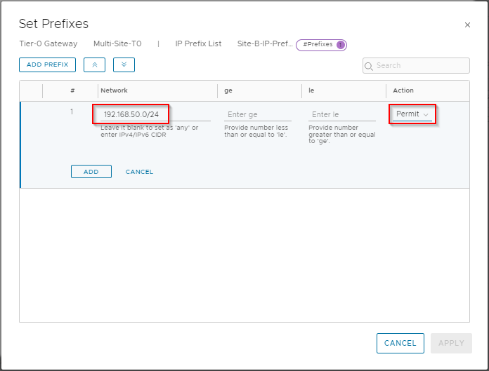
Click Add, Apply and Save to save the list. Click Close to complete.
Route Maps
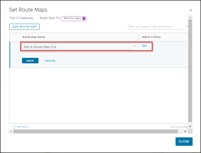
Next, Let’s create our Route Maps. From the Global NSX-T manager interface, click the three dots next to the Multi-Site-T0 gateway and select Edit.
Scroll down and expand Routing and click Set next to Route Maps. Click Add Route Map.
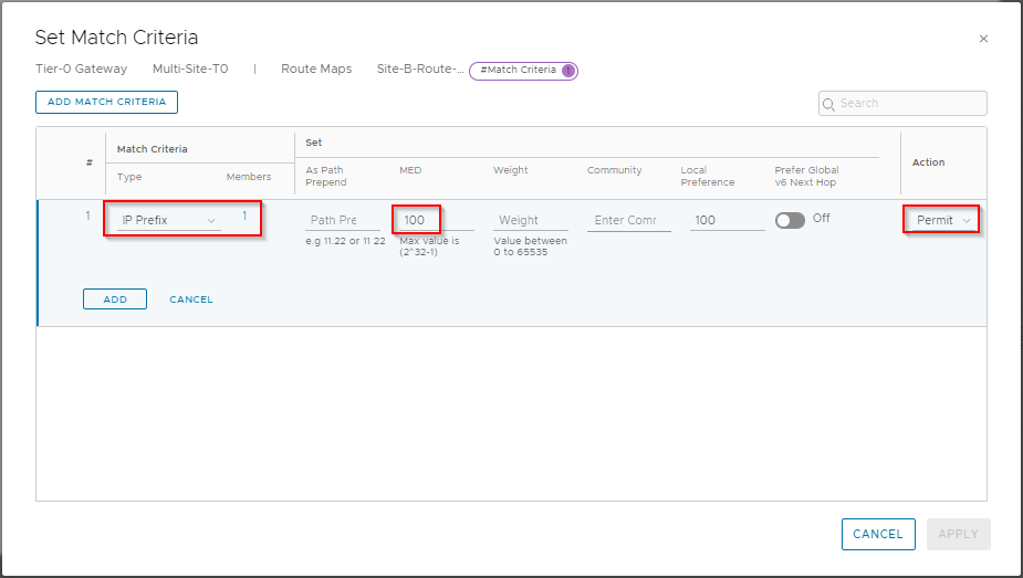
Name the map Site-A-Route-Map-Out and click Set:
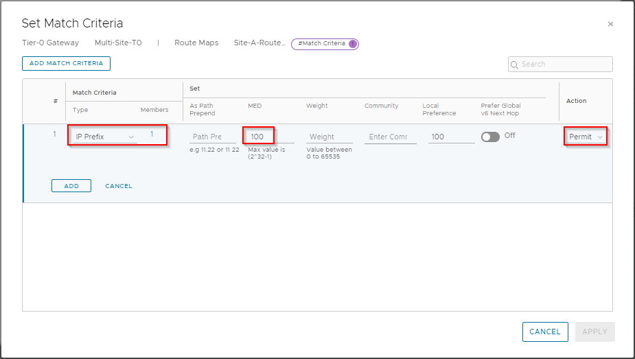
Click Add Match Criteria.
Ensure Type is set to IP Prefix and click Set. From the selection list, select Site-A-IP-Prefix-List and click Save. Back at the Set Match Criteria dialogue, enter 100 in MED value and set Action to Permit:
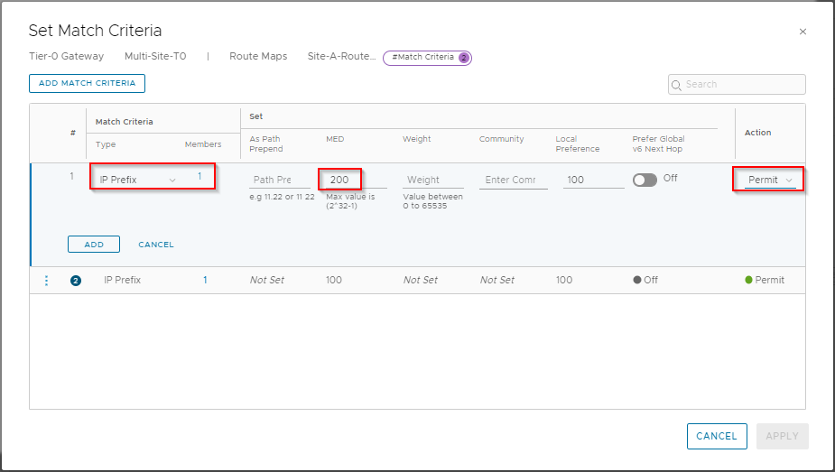
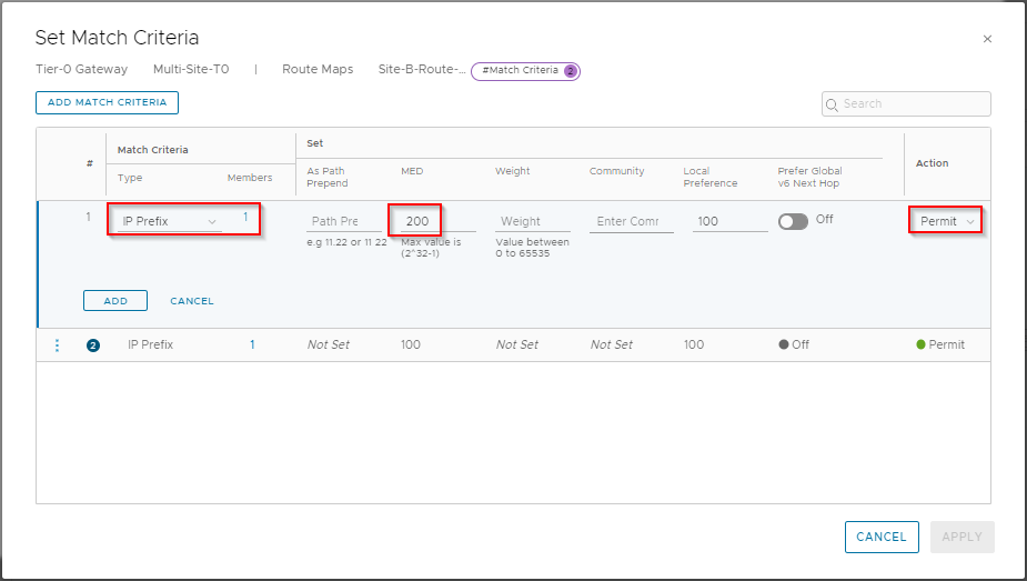
Click Add to save. Click Add Match Criteria.
Ensure Type is set to IP Prefix and click Set. From the selection list, select Site-B-IP-Prefix-List and click Save. Back at the Set Match Criteria dialogue, enter 200 in MED value and set Action to Permit:
Click Add, Apply and Save to complete.
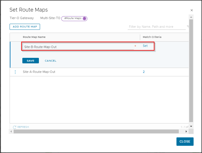
Repeat for Site B. Click Add Route Map.
Name the map Site-B-Route-Map-Out and click Set:
Click Add Match Criteria.
Ensure Type is set to IP Prefix and click Set. From the selection list, select Site-B-IP-Prefix-List and click Save. Back at the Set Match Criteria dialogue, enter 100 in MED value and set Action to Permit:
Click Add to save. Click Add Match Criteria.
Ensure Type is set to IP Prefix and click Set. From the selection list, select Site-A-IP-Prefix-List and click Save. Back at the Set Match Criteria dialogue, enter 200 in MED value and set Action to Permit:
Click Add, Apply and Save to complete.
Route Filter
Lastly, we need to hook our Route Maps into BGP. This is done with Route Filters.
From the Global NSX-T manager interface, click the three dots next to the Multi-Site-T0 gateway and select Edit.
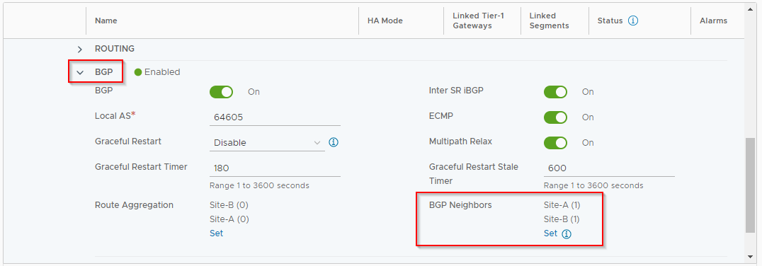
Scroll down and expand BGP and click Set next to BGP Neighbours:
Click the three dots next to 192.168.12.1 (location Site-A) and select Edit. Then click on the number under Route Filter:
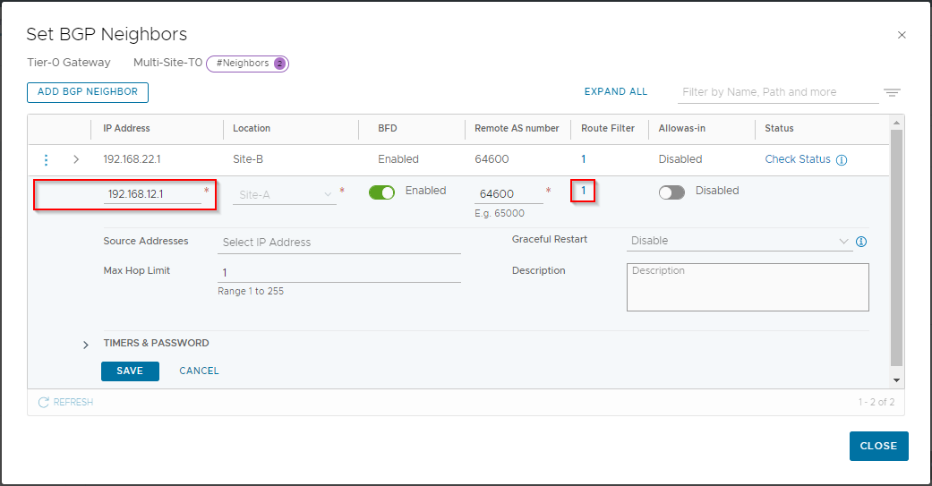
Click the three dots next to IPv4 and select Edit. Under Out Filter select Configure:
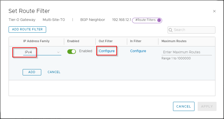
From the drop down list select Site-A-Route-Map-Out and click Save:
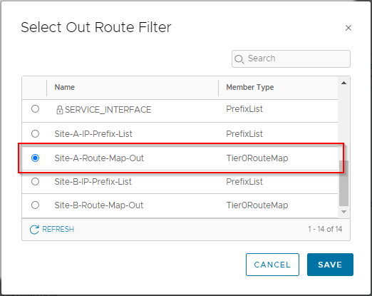
Confirm that the Out Filter is now set to “1”. Click Add, Apply and Save to complete the Site A route filter.
Let’s complete Site B’s route filter.
Click the three dots next to 192.168.12.2 (location Site-B) and select Edit. Then click on the number under Route Filter.
Click the three dots next to IPv4 and select Edit. Under Out Filter select Configure. This time select Site-B-Route-Map-Out:
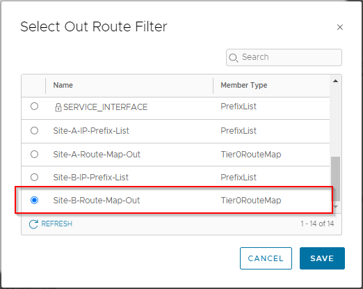
Click Save. Confirm that the Out Filter is now set to “1”. Click Add, Apply and Save to complete the Site B route filter.
Click Close to complete route filter configuration. Click Close Editing to close the configuration of the Tier-0 gateway.
Ingress Testing Recap
We did a lot of Ingress testing in Part 7, so lets do a quick test here too. First off, let’s look at the routing table on our OPNsense LABROUTER:
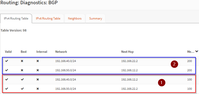
Looks good. Looking at (1), our routes with the lowest MED, our route to 192.168.40.0/24 is via 192.168.12.2 (Multi-Site-T0 Tier-0 Gateway uplink interface in Site A).
Where as our route to 192.168.50.0/24 is via 192.168.22.2 (Multi-Site-T0 Tier-0 Gateway uplink interface in Site B).
Secondary routes (2) for both networks exist on the opposite site Multi-Site-T0 Tier-0 Gateway uplink interfaces.
Let’s run some trace routes to our test VMs:
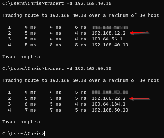
Nice! Traffic now flowing to the correct sites!
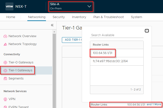
Let’s confirm where the extra hops are coming from. Looking at the Router Links dialogue of our Site A Tier-1 gateway:
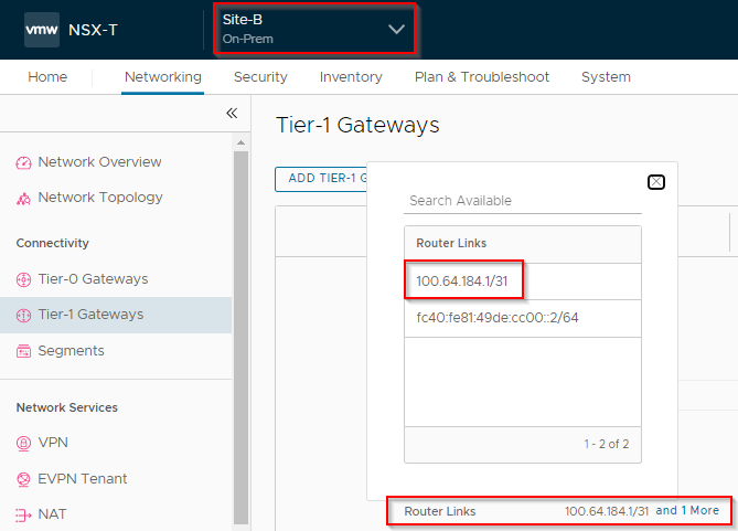
And the same for our Site A Tier-1 gateway:
Egress Testing
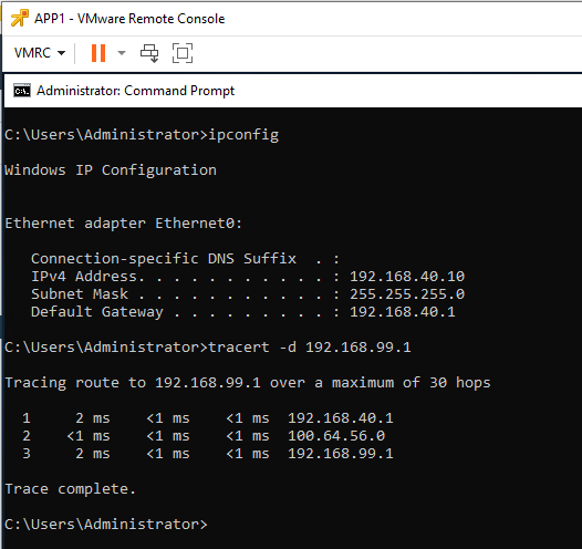
Let’s remind ourselves where our Site A test VM is located in the diagram and our preferred traffic flow out of the environment:
 Testing from our Site A test VM up to 192.168.99.1, a machine on our Wider LAN:
Finally, testing from a Site B test VM is located in the diagram and our preferred traffic flow out of the environment:
Testing from our Site B test VM up to 192.168.99.1, a machine on our Wider LAN:
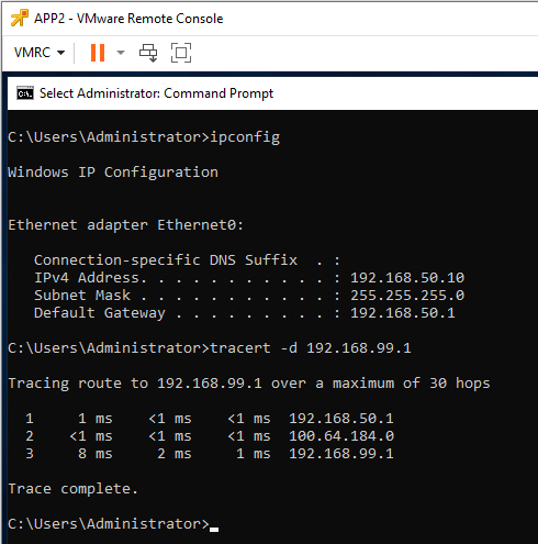
Yep that’s working perfectly!
Ingress and Egress traffic flowing via our preferred routes.
Conclusion and Wrap Up
So there we have it. In this post we fixed our outstanding BGP problem from Part 7. We were able to prove that our ingress traffic flow was fixed too. Finally we were also able to demonstrate that our egress traffic was exiting the environment via it’s preferred site.
This was part 8 of a multipart series. Find the other parts here:
- Part 1: Lab Setup and Overview
- Part 2: Site A Build
- Part 3: Automated Site B Build
- Part 4: NSX-T Site Federation
- Part 5: Remote Tunnel Endpoints
- Part 6: Federated Tier-0 Gateway
- Part 7: Federated Tier-1 Gateways
- Part 8: This Part: Egress Traffic and MEDdling with BGP
That will be it for our NSX-T Overlay Lab Build series.
-Chris