


 In this post we will create our uplink segments, deploy our Tier-0 gateway and establish our BGP connections to our lab router.
This post is part 6 of a multipart series. Find the other parts here:
- Part 1: Lab Setup and Overview
- Part 2: Site A Build
- Part 3: Automated Site B Build
- Part 4: NSX-T Site Federation
- Part 5: Remote Tunnel Endpoints
- Part 6: This Part: Federated Tier-0 Gateway
- Part 7: Federated Tier-1 Gateways
- Part 8: Egress Traffic and MEDdling with BGP
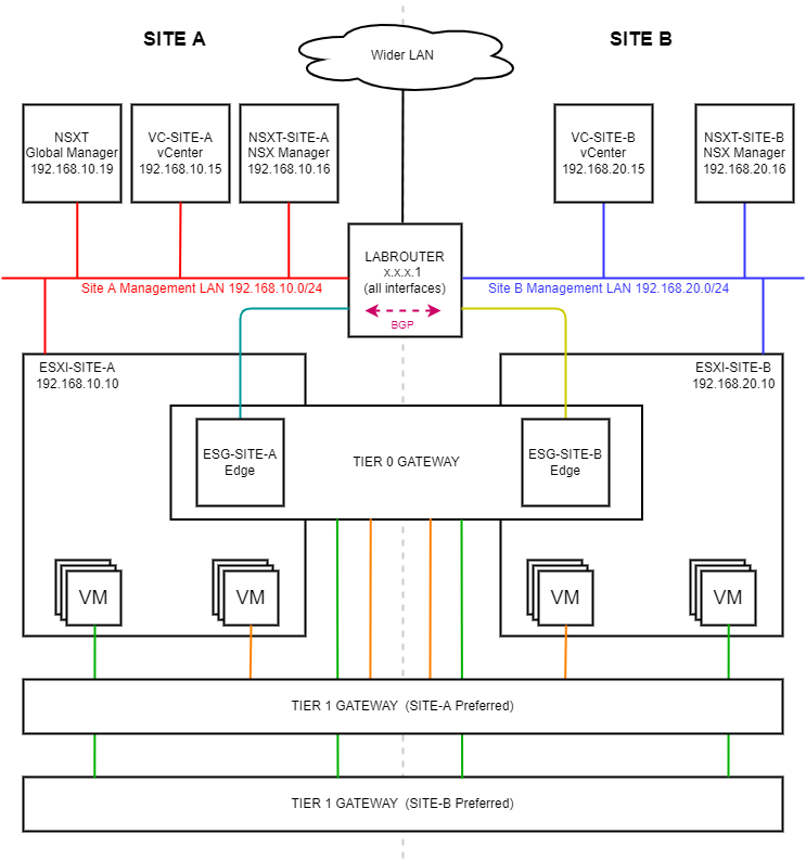
As a reminder, in this series we will be building the following lab:
 (Click image to zoom in)
Overview
What is a Tier-0 Gateway?
A Tier-0 gateway performs the functions of a Tier-0 logical router. It processes traffic between the logical and physical networks; that is northbound traffic headed out from the NSX-T environment and southbound traffic headed in to the NSX-T environment. As the Tier-0 is federated, it is able to perform this function at both our Site A and Site B sites.
Set Overlay Transport Zones as Default
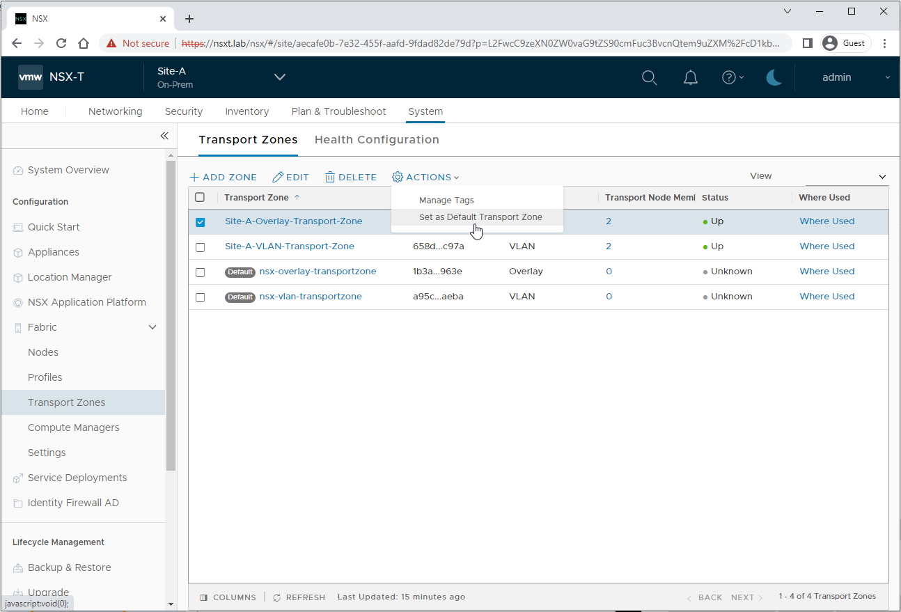
As we are using our own transport zones way that we created back in Part 2 and Part 3 rather than using the pre-defined system created zones, we need to set ours as the defaults.
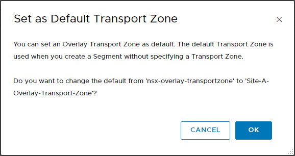
Log into the Global NSX-T Manager and select Site-A from the task bar drop down. From there, select System > Fabric > Transport Zones. Select Site-A-Overlay-Transport-Zone > Actions > Set as Default Transport Zone:
Click OK when prompted:
Repeat the above for Site B and Site-B-Overlay-Transport-Zone.
Create Uplink Segments
Lets create our Tier-0 uplink segments. These will be used for north/south traffic to and from the federated gateway to the site edges.
Select the Global Manager from the task bar drop down. From there, select Networking > Segments then select Add Segment.
Name the segment Site-A-Uplink, ensure connected gateway is None. Select Location Site-A and Site-A-VLAN-Transport-Zone. Finally, set VLAN to 12 as defined in Part 1:
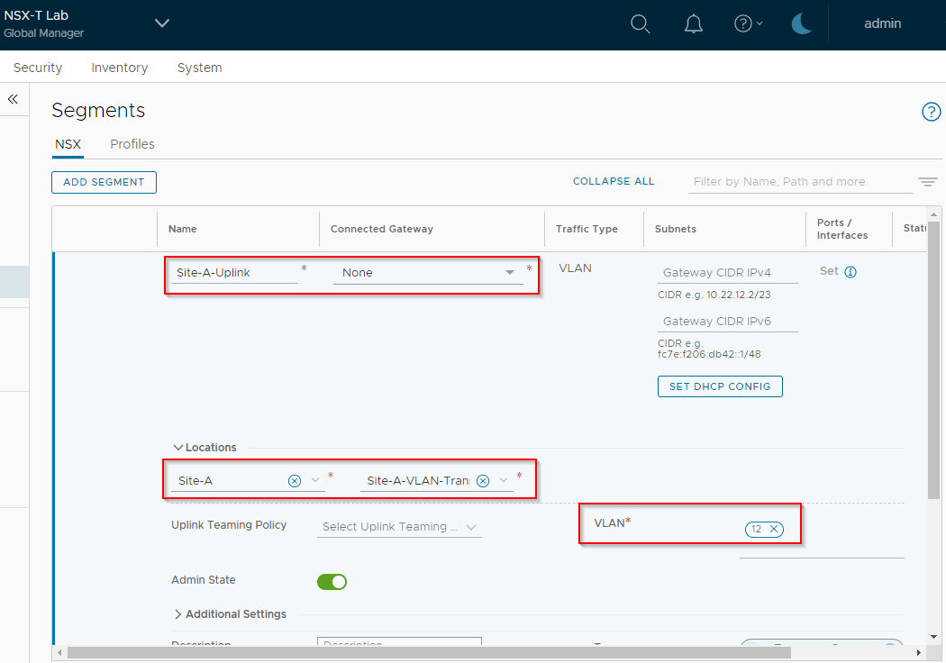
Click Save and No to complete.
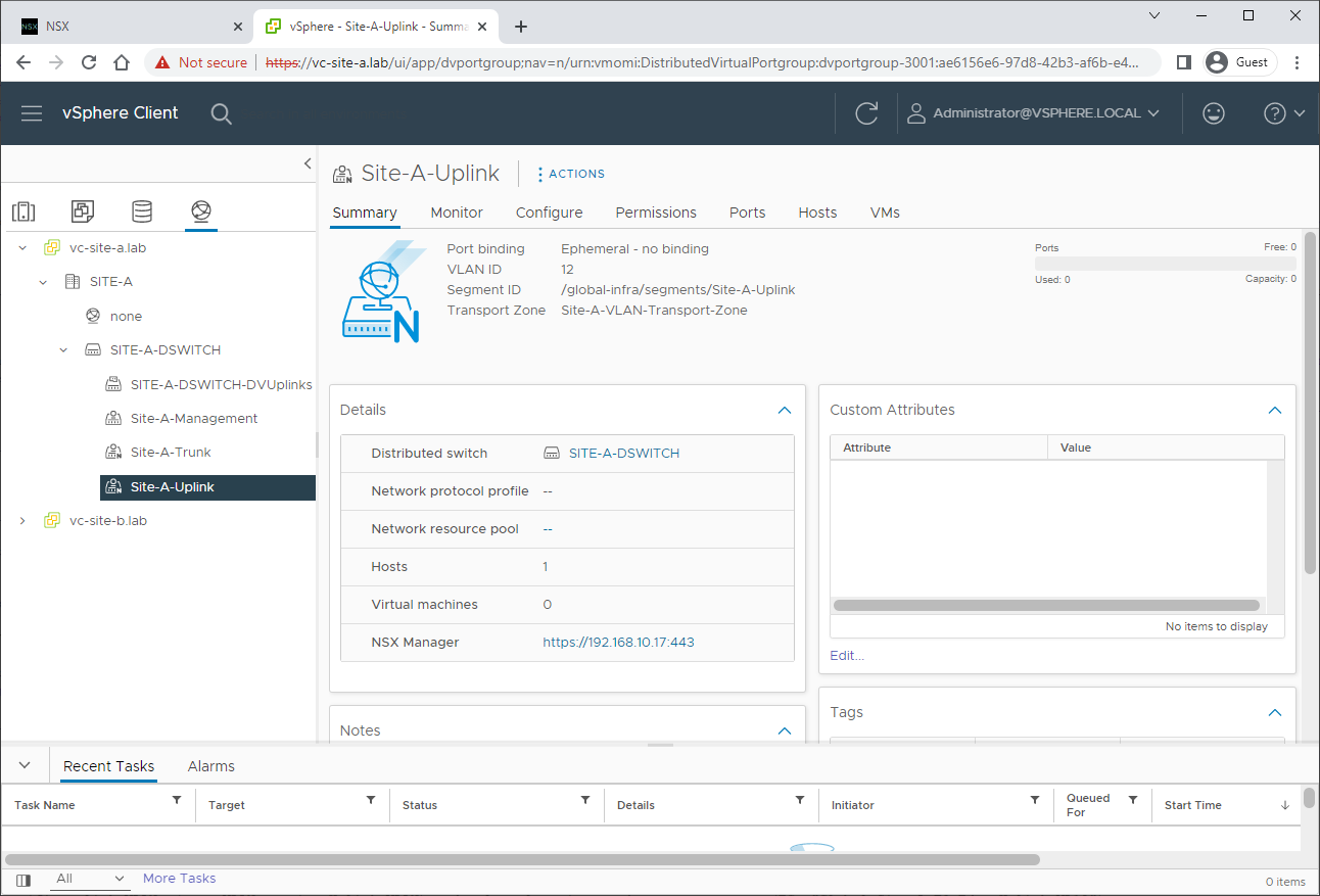
A quick peek at Site A’s vCenter networking confirms creation:
Repeat for Site B, naming the uplink Site-B-Uplink, location as Site-B, selecting Site-B-VLAN-Transport-Zone and setting VLAN to 22 (again as defined in Part 1):
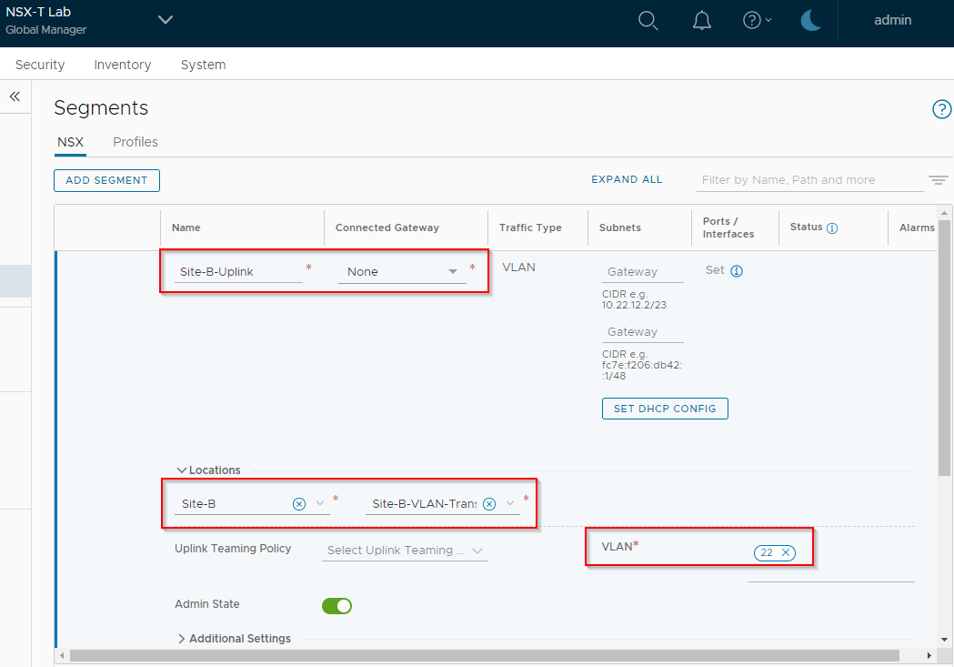
Yep, looks good:

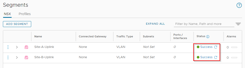
Back in NSX-T Global Manager, clicking Check Status returns Success for both:
Create Tier-0 Gateway
Lets create the federated Tier-0 gateway. Select the Global Manager from the task bar drop down. From there, select Networking > Tier-0 Gateways. Select Add Tier-0 Gateway.
Name the Gateway Multi-Site-T0, set the HA mode to Active, mark all locations as primary (i.e. both sites active rather than one active and one standby) and finally add both locations and edge clusters:
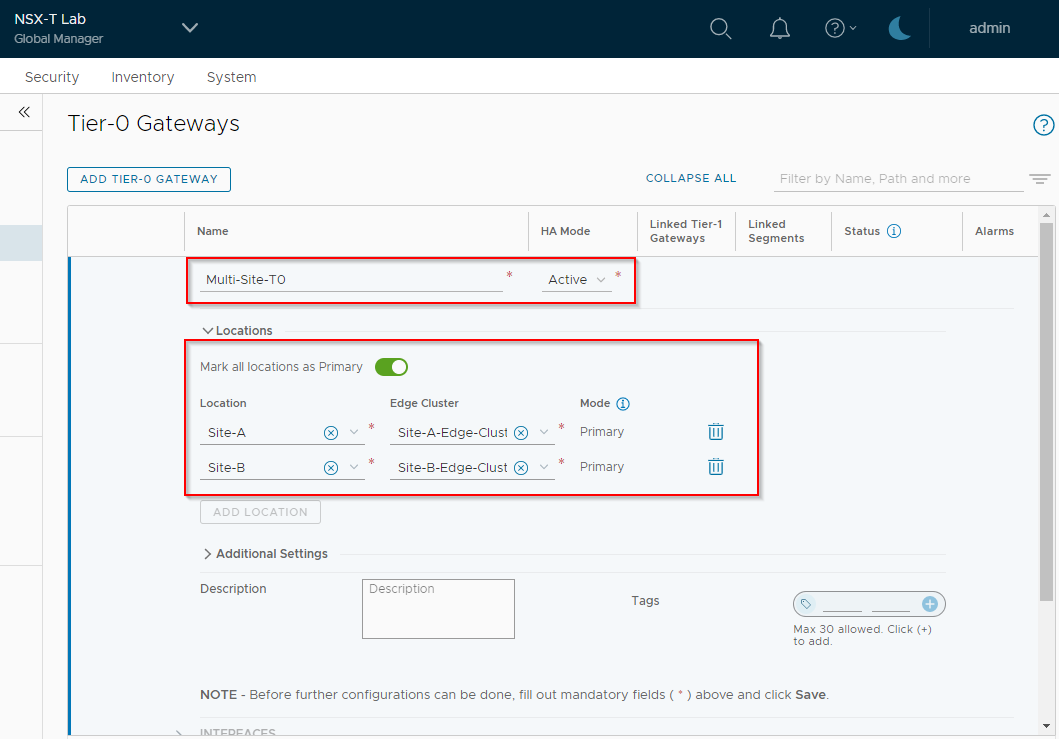
Click Save and Yes to continue the configuration of the Tier-0.
Scroll down to Interfaces, expand and click Set.
Click Add Interface, name the interface Site-A-Uplink, location Site-A, IP address of 192.168.12.2/24 (again as defined in Part 1), connected to Site-A-Uplink, edge node ESG-SITE-A:
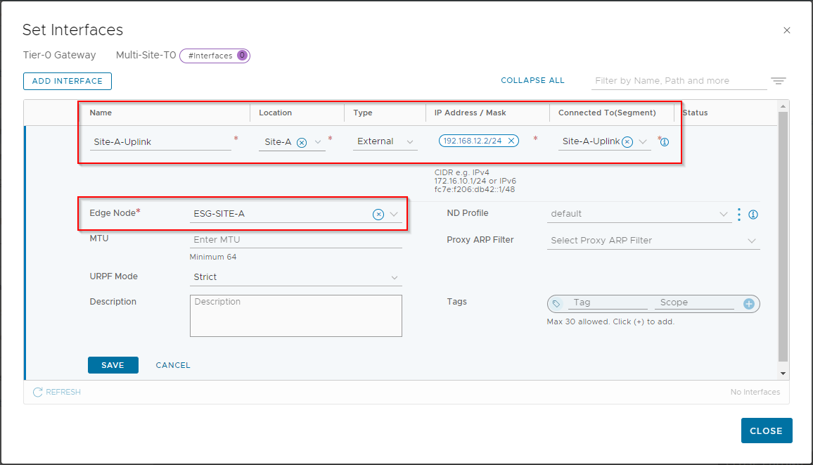
Click Save.
Click Add Interface , name the interface Site-B-Uplink, location Site-B, IP address of 192.168.22.2/24 (again as defined in Part 1), connected to Site-B-Uplink, edge node ESG-SITE-B:
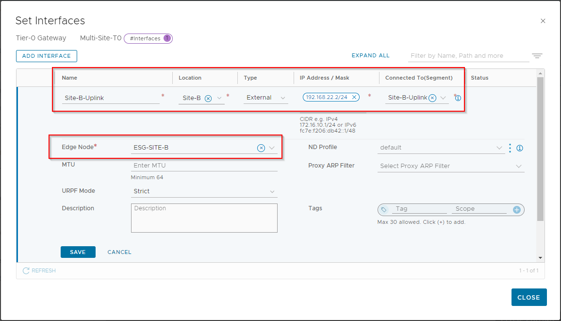
Click Save. Again, click Check Status to confirm that the configuration is correct:
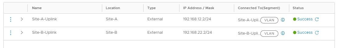
Click Close. Once back in the Multi-Site-T0 configuration, confirm that both sites have one interface each:
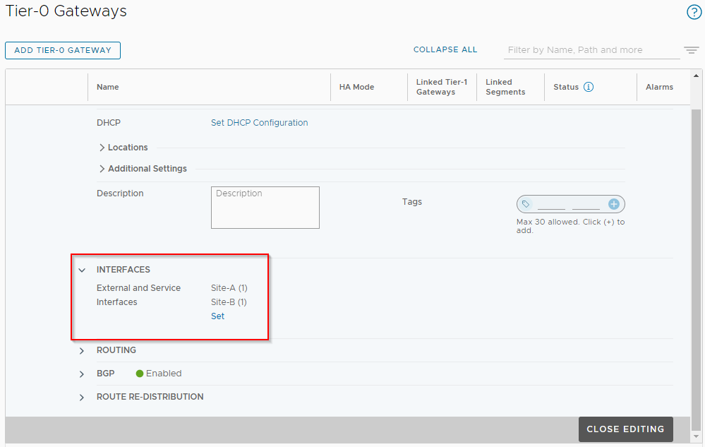
Next, scroll down to Route Re-distribution and click Set next to Site-A.
Click Add Route Re-distribution, Enter name of Site-A-Route-Redistribution and click Set. Select options as shown below and click Apply:
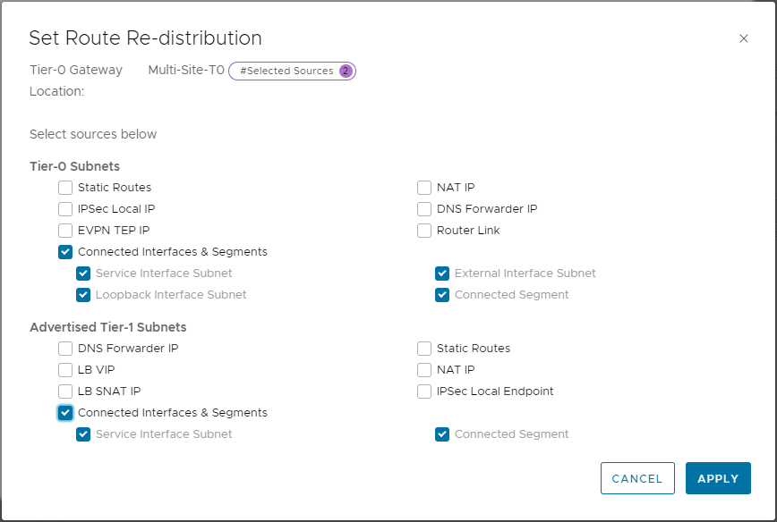
Click Add and Apply to save.
Repeat route re-distribution settings for Site B and ensure both are enabled:

Click Save. Scroll back up within the configuration of Multi-Site-T0, and open the BGP section.
Set Local AS to 64605 and Graceful Restart to Disable:
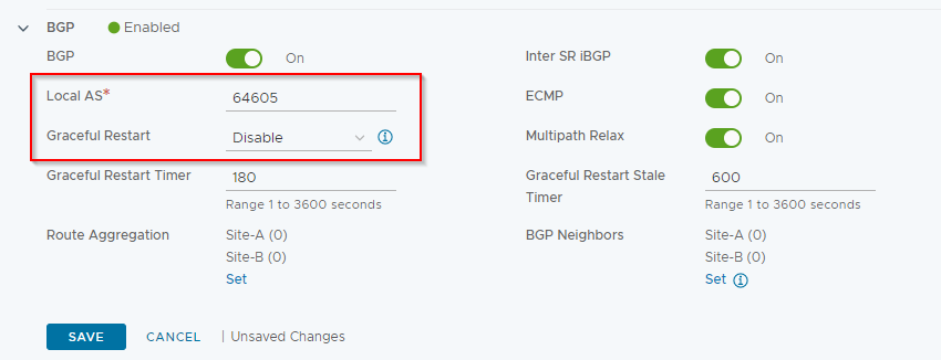
Click Save.
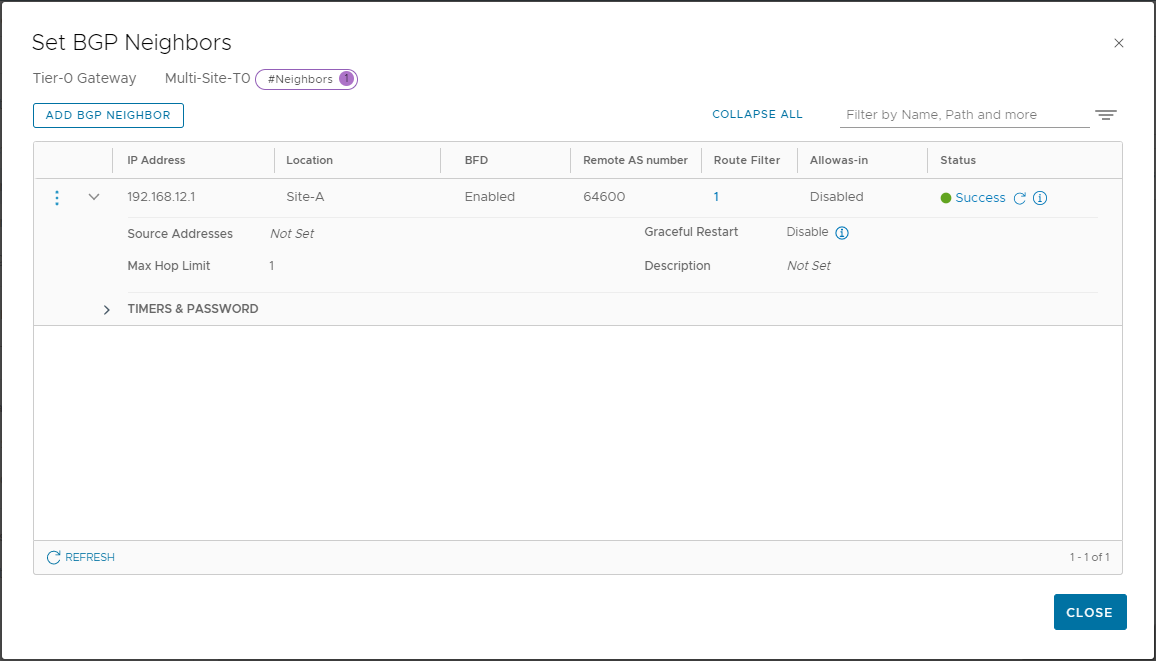
Set under BGP Neighbours and select Add BGP Neighbour
Enter 192.168.12.1, set Location to Site-A, set BFD Enabled. As per OPNsense BGP and BFD Configuration we know that our OPNsense Labrouter has a BGP AS of 64600, so add that as Remote AS Number:

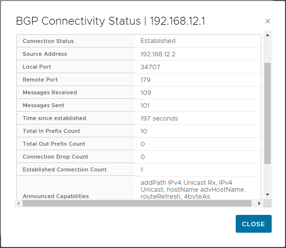
Click Save. Click Check Status to confirm BGP has established:
Click i to show further information and confirm “Established” status:
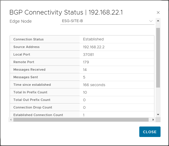
Click Add BGP Neighbour and configure for Site B location. As we are using Lab router as our site B uplink, set IP to 192.168.22.1 and remote AS as 64600 also:
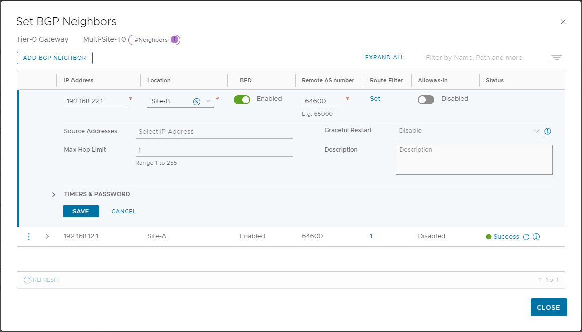
Click Save. Click Check Status to confirm BGP has established:
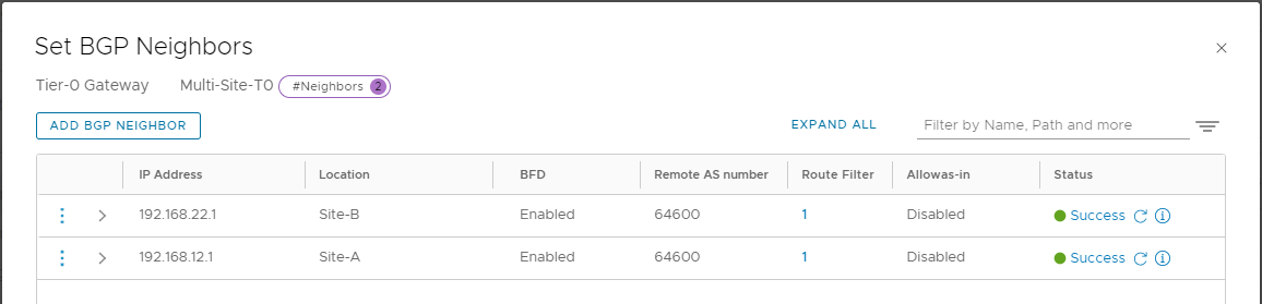
Again, click i to show further information and confirm “Established” status:
Click Close to close BGP Neighbours setting and Close Editing to close Tier-0 configuration.
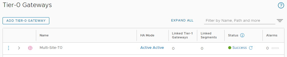
Finally, click Check Status on the Multi-Site-T0 gateway and confirm Success status:
Nice. And as some “icing on the cake”, lets check our BGP summary in OPNsense:
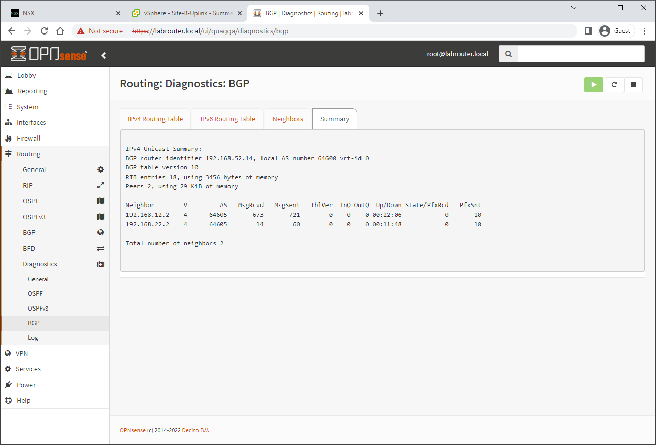
Two established neighbours! Perfect!
Conclusion and Wrap Up
So there we have it. Our Tier-0 router has been deployed and configured. BGP has been established at both sites from the Tier-0 gateway up through the edges and uplinks to our Labrouter. Our last task is to deploy two Tier-1 gateways and we will look to complete that in part 7.
This was part 6 of a multipart series. Find the other parts here:
- Part 1: Lab Setup and Overview
- Part 2: Site A Build
- Part 3: Automated Site B Build
- Part 4: NSX-T Site Federation
- Part 5: Remote Tunnel Endpoints
- Part 6: This Part: Federated Tier-0 Gateway
- Part 7: Federated Tier-1 Gateways
- Part 8: Egress Traffic and MEDdling with BGP
Look out for future parts coming soon!
-Chris