 Here we go then, eyes down for our second look at NSX-T.
If you missed the first look, have a read now: NSX-T 3.2: Micro-Segmentation Only Deployment - Manual Setup Its a cracking read honest! ![]()
In this series of posts, we’ll be looking at deploying NSX-T 3.2 into a lab environment. Within the lab we will be emulating a two site enterprise with active services running from either site. On to of that, we will configure stretched layer 2 networking that will allow for us to host and failover services from one site to the other without the need for reconfiguration of those services.
This post is part 1 of a multipart series. Find the other parts here:
- Part 1: This part - Lab Setup and Overview
- Part 2: Site A Build
- Part 3: Automated Site B Build
- Part 4: Multi Site Federation
- Part 5: Remote Tunnel Endpoints
- Part 6: Federated Tier-0 Gateway
- Part 7: Federated Tier-1 Gateways
- Part 8: Egress Traffic and MEDdling with BGP
Right then, lets get on with part 1 of the series and take a look at the lab setup.
Overview
The NSX-T Dual Site Lab Diagram
In this series we will be creating following lab:
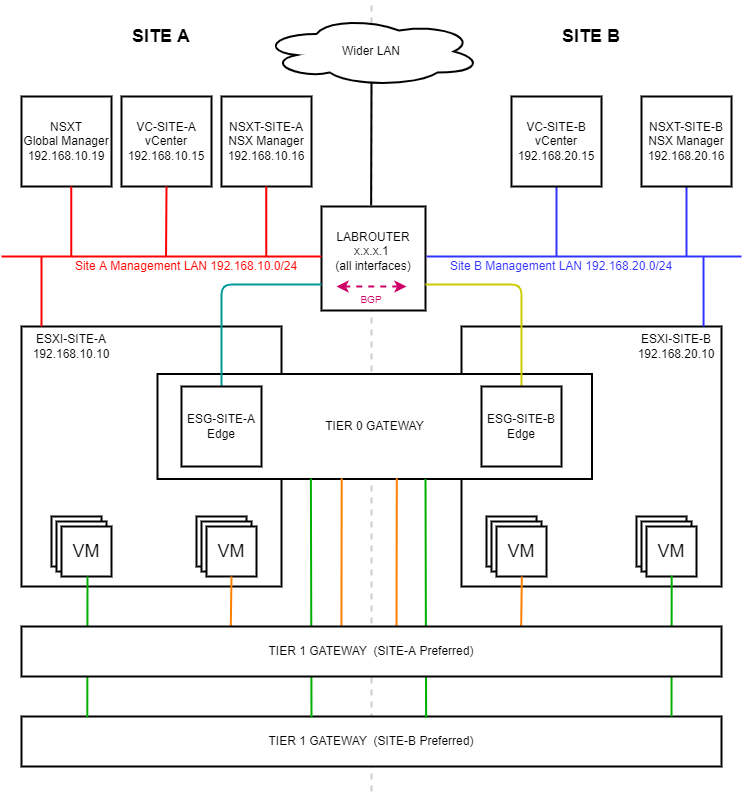 (Click image to zoom in)
A dual site setup consisting of (imaginatively named) sites “SITE A” and “SITE B”. The grey dotted line running down the middle of the diagram represents the demarcation between the sites.
Lab Components
Lets work our way around the lab to understand the layout. Starting top left.
NSXT Global Manager - This is our federated NSX-T manager. This manager provides us our single point of management and control for the three NSX-T managers located in the lab (including the this Global Manager). The global manager is also used to apply networking configuration that spans both sites. Read more here: NSX Federation.
VC-SITE-A / VC-SITE-B - vSphere 7 vCenter servers for each site. Both vCenter servers are in enhance link mode. Read more here: vCenter Enhanced Linked Mode.
NSXT-SITE-A / NSXT-SITE-B - The local NSX-T manager responsible for the management and control of local NSX-T resources based in their respective site.
Wider LAN - The rest of my home network. Nothing to see here, move along…
LABROUTER - An OPNsense router the configuration of which is discussed here: OPNsense BGP and BFD Configuration.
ESXI-SITE-A / ESXI-SITE-B - The ESXi host running the our production VMs and NSX-T edge located in either site.
TIER 0 GATEWAY - A cross site stretched top level logical router that spans across both sites A and B. Read more here: Tier-0 Logical Router.
ESG-SITE-A / ESG-SITE-B - Our (singular) NSXT-T edge. This being a lab, we only need one edge per site. Production deployments would (SHOULD!) have more than one edge per site. Read more here: Create an NSX Edge Transport Node.
VMs - Our production VMs connected to either of our Tier 1 gateways / logical routers.
TIER 1 Gateway (SITE-A Preferred): A cross site stretched logical router that spans both sites A and B. Ingress / Egress traffic to VMs connected to this gateway is preferentially routed to run through Site A with failover to Site B should it be required. Read more here: Tier-1 Logical Router.
TIER 1 Gateway (SITE-B Preferred): A cross site stretched logical router that spans both sites A and B. Ingress / Egress traffic to VMs connected to this gateway is preferentially routed to run through Site B with failover to Site A should it be required. Read more here: Tier-1 Logical Router.
Lab Networking Configuration
Being that the lab is a collapsed NSX-T setup - that is our edge VMs are running alongside our production VMs on our ESXi hosts - we need to make fairly extensive use of VLANs to segregate traffic to and from our NSX-T lab.
As per NSX-T Edge TEP networking options (83743): Edge TEP and ESXi host TEP can be configured on the same VLAN in the following configurations:
- Edge VM TEP interface connected to a logical switch on a vDS7 with NSX-T 3.1.0 or above
The lab is being built with vSphere 7 and NSX-T 3.2. We will be sharing TEP VLAN for our hosts and our edges.
Site A VLANs and Subnets
The following VLANs and subnets are used on Site A:
| VLAN ID | Subnet | Use | OPNsense Interface | Colour in Diagram |
|---|---|---|---|---|
| 1 | 192.168.10.0/24 | Management Traffic | SITE_A_MGMT | Red |
| 11 | 192.168.11.0/24 | Transport End Points (TEPS) | SITE_A_TRANSPORT_VL11 | Light Blue |
| 12 | 192.168.12.0/24 | Uplinks | SITE_A_UPLINK_VL12 | Light Blue |
| 13 | 192.168.13.0/24 | Remote Transport End Points (RTEPS) | SITE_A_RMOTE_TRANSPORT_VL13 | Light Blue |
Site A IP Allocation
The following IP allocations are in use on Site A:
| IP Address | VLAN ID | Use |
|---|---|---|
| 192.168.10.10 | 1 | ESXI-SITE-A Management Interface |
| 192.168.10.15 | 1 | VC-SITE-A Management Interface |
| 192.168.10.16 | 1 | NSXT-SITE-A Management Interface |
| 192.168.10.17 | 1 | VC-SITE-A Management (Cluster Virtual IP) |
| 192.168.10.19 | 1 | NSXT Global Management Interface |
| 192.168.10.22 | 1 | ESG-SITE-A Management Interface |
| 192.168.11.2-254 | 11 | Site A Tunnel End Point (TEP) Pool |
| 192.168.12.2 | 12 | Global Tier 0 Uplink - Site A |
| 192.168.13.2-254 | 13 | Site A Remote Tunnel End Point (RTEP) Pool |
Site B VLANs and Subnets
The following VLANs and subnets are used on Site B:
| VLAN ID | Subnet | Use | OPNsense Interface | Colour in Diagram |
|---|---|---|---|---|
| 1 | 192.168.20.0/24 | Management Traffic | SITE_B_MGMT | Blue |
| 21 | 192.168.21.0/24 | Transport End Points (TEPS) | SITE_B_TRANSPORT_VL21 | Dark Yellow |
| 22 | 192.168.22.0/24 | Uplinks | SITE_B_UPLINK_VL22 | Dark Yellow |
| 23 | 192.168.23.0/24 | Remote Transport End Points (RTEPS) | SITE_B_RMOTE_TRANSPORT_VL23 | Dark Yellow |
Site B IP Allocation
The following IP allocations are in use on Site A:
| IP Address | VLAN ID | Use |
|---|---|---|
| 192.168.20.10 | 1 | ESXI-SITE-B Management Interface |
| 192.168.20.15 | 1 | VC-SITE-B Management Interface |
| 192.168.20.16 | 1 | NSXT-SITE-B Management Interface |
| 192.168.20.17 | 1 | VC-SITE-B Management (Cluster Virtual IP) |
| 192.168.20.22 | 1 | ESG-SITE-B Management Interface |
| 192.168.21.2-254 | 21 | Site B Tunnel End Point (TEP) Pool |
| 192.168.22.2 | 22 | Global Tier 0 Uplink - Site B |
| 192.168.23.2-254 | 23 | Site B Remote Tunnel End Point (RTEP) Pool |
Lab Router Configuration
Looking at interfaces as configured on LABROUTER:
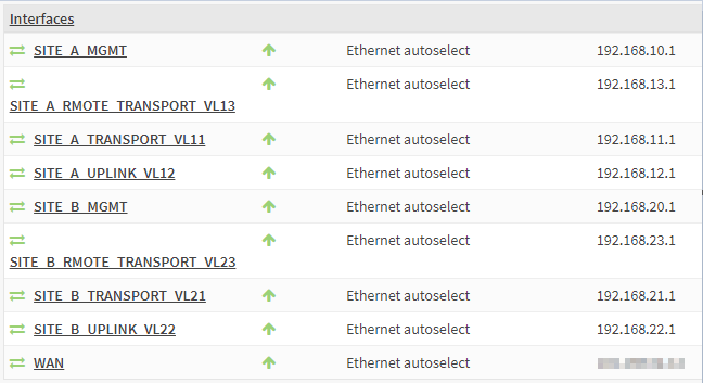
As previously detailed, the .1 IP address of each subnets are assigned to the interfaces and VLANs configured on the lab router.
The WAN interface is used for connectivity to the rest of my home network.
The only other in use services running on the lab router are:
- Unbound DNS: Used for name resolution within the lab
- NTP: Time synchronization
- FRR BGP and BFD: Used for receiving and sending routing info from and to the lab
Checkout OPNsense BGP and BFD Configuration for further details
Top Level Configuration
Unsurprisingly, I’m running this whole setup as a “nested” deployment:
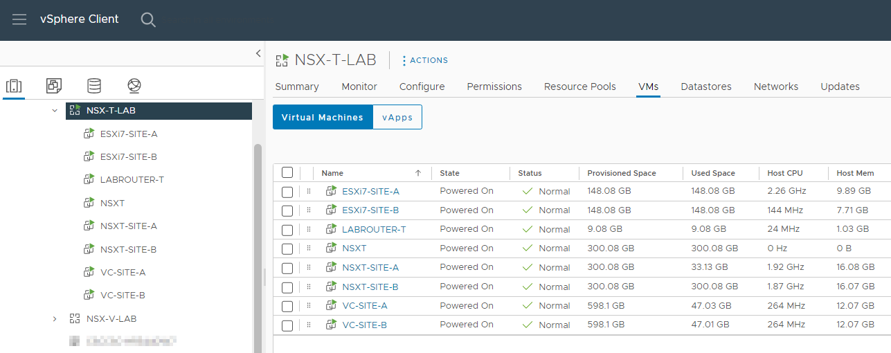
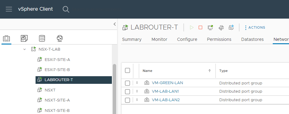
Looking closer at the top level networks used by the lab, there are just the three:
- VM-GREEN-LAN: Provides “WAN” connectivity for the lab up to the rest of my home network.
- VM-LAB-LAN1: Connectivity for all servers on Site A
- VM-LAB-LAN2: Connectivity for all servers on Site B
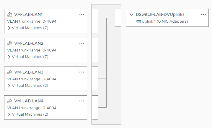
VM-LAB-LAN3 and VM-LAB-LAN4 are not used in this Lab.
Looking closer at the Lab Distributed switch, no uplinks to the outside world:
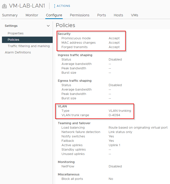
All lab portgroups set with the following security with VLAN trunking enabled:
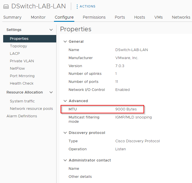
MTU is set to 9000:
Lab vCenter Configuration
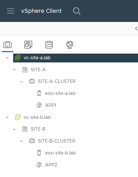
Lets look at the vCenter configuration. Clusters view; Nothing complicated, two linked vCenters, two hosts and a test APP VM per site:
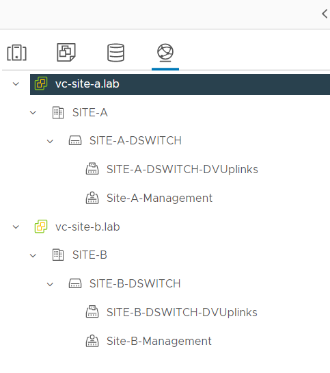
Networking overview, again, nothing complicated, one distributed switch per site:
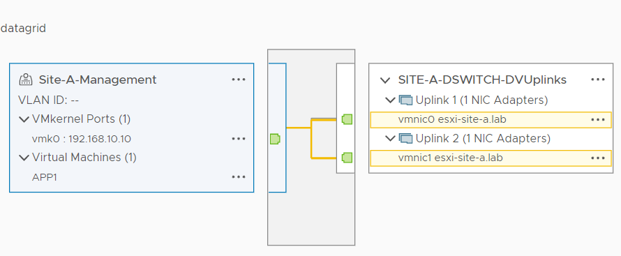
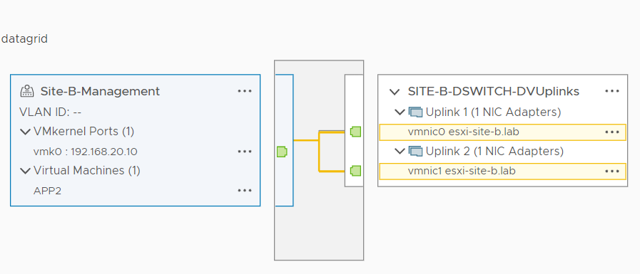
Finally, looking closer at the configuration of the single untagged portgroup per site for management traffic. Site A:
Site B:
Conclusion and Wrap Up
That’ll just about do it for the first post of the series. Sure, on it’s own this post is a little dry, however as we get to building out our NSX-T lab, this post will come into its own for reference purposes down the line.
This was part 1 of a multipart series. Find the other parts here:
- Part 1: This part - Lab Setup and Overview
- Part 2: Site A Build
- Part 3: Automated Site B Build
- Part 4: Multi Site Federation
- Part 5: Remote Tunnel Endpoints
- Part 6: Federated Tier-0 Gateway
- Part 7: Federated Tier-1 Gateways
- Part 8: Egress Traffic and MEDdling with BGP
Look out for future parts coming soon!
-Chris

