 Last time we looked at how our Nutanix cluster ingests our data into it’s Distributed Storage Fabric (DSF) and the concepts behind the ingestion. This time we will look at how the DSF protects the ingested data within the cluster.
If you missed the previous post, you can find it here: Nutanix Distributed Storage Fabric Concepts.
I’m going to call it before we get into the weeds: Having two concepts with the the same acronym “RF” is… confusing. In blogs, discussion threads and some third party media, “RF” can mean either Redundancy Factor OR Replication Factor. Thus descriptions and meanings get real confusing real quick!
Anyway, let’s get to it.
Overview
Availability Domains / Fault Tolerance Domains
Analogous to VMware vSAN Fault Domains.
A Nutanix cluster leveraging DSF can be configured to tolerate one or two failures (depending on the replication factor of the cluster or container) of a variety of hardware components while still running guest VMs and responding to commands through the management console.
These failures can be be thought of in terms of fault domains. There are four fault domains in a Nutanix Cluster:
- Disk
- Node
- Block
- Rack
Looking at our Nutanix AHV node we deployed previously:
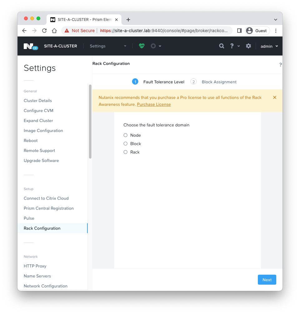 We have one node, therefore not many options!
Redundancy Factor (Hardware)
Redundancy factor refers to the number of hardware failures (such as a node failure or a disk failure) that a cluster is able to withstand while still continuing to operate. By default, Nutanix clusters (with the recommended minimum of 3 nodes) have a redundancy factor of 2. This means they can tolerate the failure of a single availability domain (disk, node, etc).
Redundancy factors of 1 and 3 are also available as a configurable options. A redundancy factor of 1 means that the cluster is not redundant; one disk or node failure will cause the cluster to fail.
A redundancy factor 3 on the other hand, allows a cluster to withstand the failure of two availability domains. However, it is important to note that:
- A cluster must have at least five availability domains for redundancy factor 3 to be enabled.
- For guest VMs to tolerate the simultaneous failure of two availability domains, the data must be stored on storage containers with replication factor 3. In other words, it is not possible to configure a replication factor higher than the current redundancy factor.
Replication Factor (Data)
Analogous to VMware vSAN Policies.
Replication factor refers to the number of copies of data and metadata that will be maintained on a cluster.
A replication factor of 2 means that 2 copies of data will be available (1 original and 1 copy), while replication factor 3 means that 3 copies of data will be available (1 original and 2 copies). While replication factor 1 is available (only the original data will be maintained, with no copies) it is not recommended unless your cluster is running applications that provide their own data protection or high availability.
As discussed here in the previous post, the OpLog acts as a staging area to absorb incoming writes onto the low-latency SSD tier. When data is written to a local OpLog, it is synchronously replicated to another one or two Nutanix CVM’s OpLog (one other OpLog for RF2 and two other OpLogs for RF3) before being acknowledged as a successful write to the host. This ensures that the data exists in at least two or three independent locations and is fault tolerant.
It is important to note that replication factor is handled differently for data and metadata.
- For data RF2, there will be two copies of data and three copies of metadata.
- For data RF3, there will be three copies of data and five copies of metadata.
Metadata replication factor cannot be set or configured independently of data replication factor, and is dependent on data replication factor and the cluster’s redundancy factor.
If you are still unsure on the two RF’s, here’s a five minute video that should help:
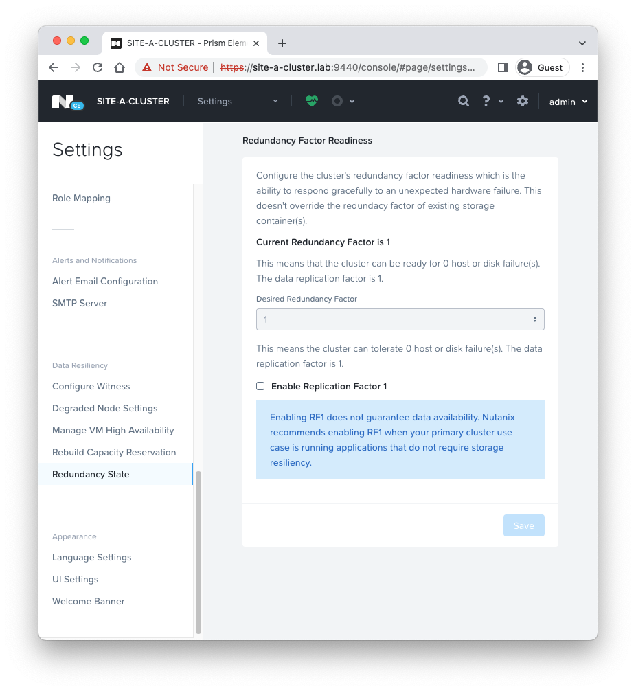
Looking at our Nutanix AHV node we deployed previously:
 And our storage containers:
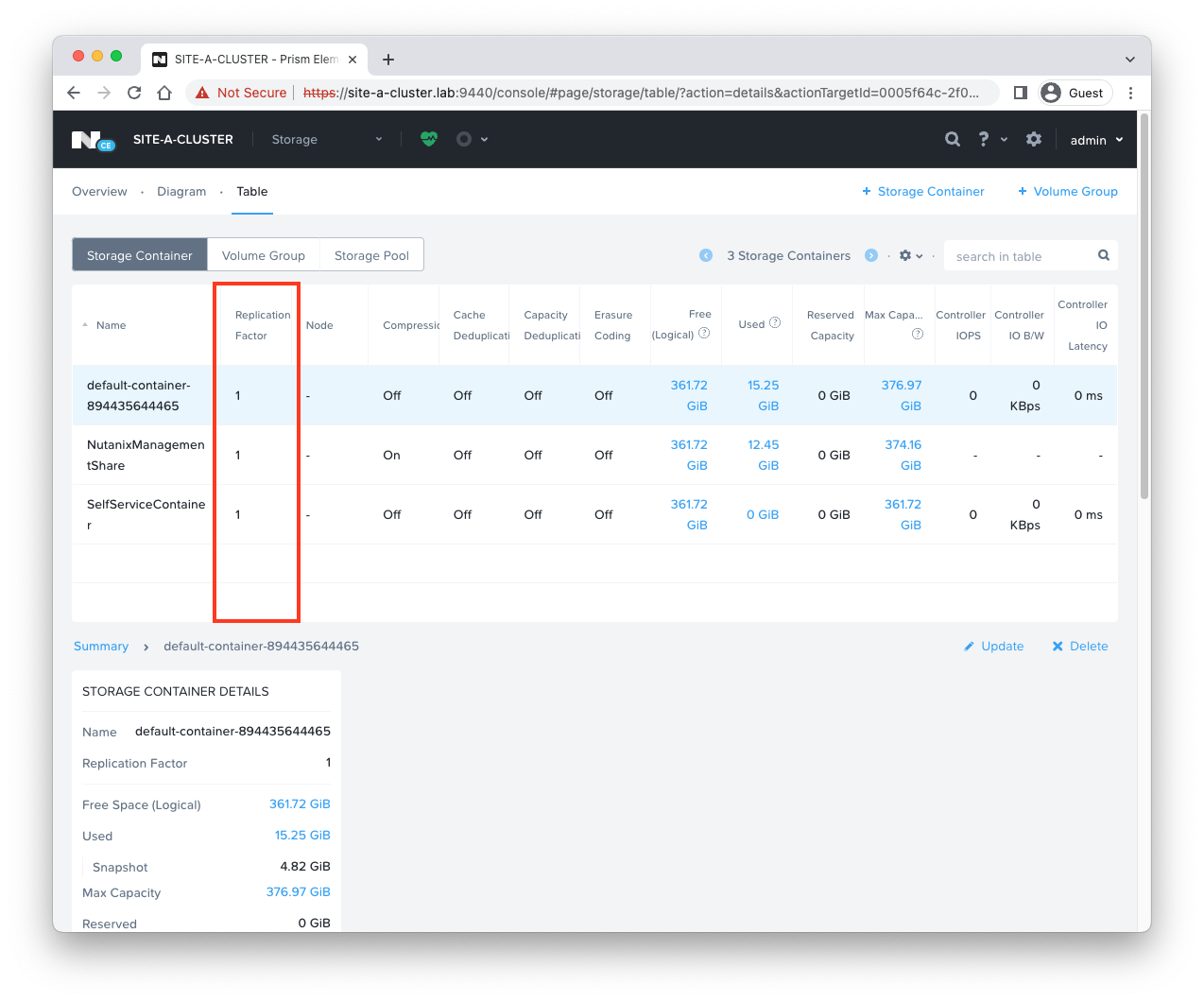 One AHV node so a redundancy factor of 1 and a replication factor of 1 across the board.
Erasure Coding
Analogous to VMware vSAN RAID 5 or RAID 6 Erasure Coding.
As cluster membership sizes increase, we can change the replication factor from 2 to 3 to handle additional failures. This increase, of course, reduces usable disk space by creating additional redundant copies of the data.
Nutanix addresses this drawback with the Erasure Coding (EC-X) feature, which increases usable disk space while maintaining the same cluster resiliency by striping individual data blocks and associated parity blocks across nodes rather than disks, forming an erasure strip.
In the event of a failure, the system uses the parity block along with the remaining blocks in the erasure strip to recalculate the missing data onto a new node. All blocks associated with erasure coding strips are stored on separate nodes. Each node can then take part in subsequent rebuilds, which reduces potential rebuild time.
EC-X works best on cold data, archives, and backups. Containers with applications that incur numerous overwrites, such as log file analysis or sensor data, require a longer delay than the one-hour EC-X post-processing default.
Trying to enable EC-X on the default storage container of our previously deployed node:
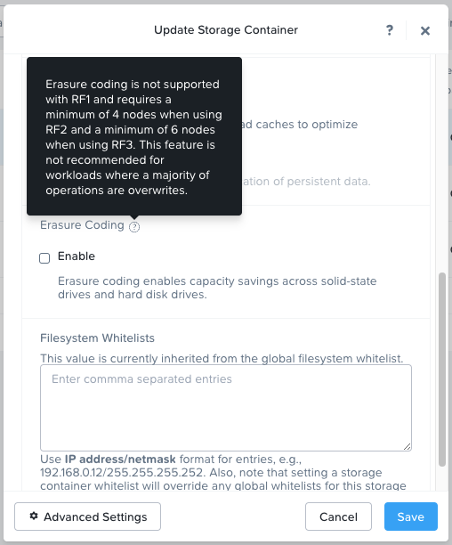
Notice the change in node requirements too!
Data Locality, Networking and I/O
VMware’s take on vSAN Data Locality.
The DSF ensures that as much of a VM’s data as possible is stored on the node where the VM is currently running. This removed the need for storage I/O to traverse the network. VM data is served locally from the CVM and stored preferentially on local storage.
Like vSAN, a Nutanix cluster does not require a backplane for inter-node communication. A standard 10GbE network is all that is required. All storage I/O for VMs running on a Nutanix node is handled by the hypervisor on a dedicated private network.
When a VM is moved from one node to another using vMotion or live migration (or during an HA event), the migrated VM’s data automatically follows the VM in the background based on read patterns.
The following diagram from the Nutanix Bible covers this nicely:
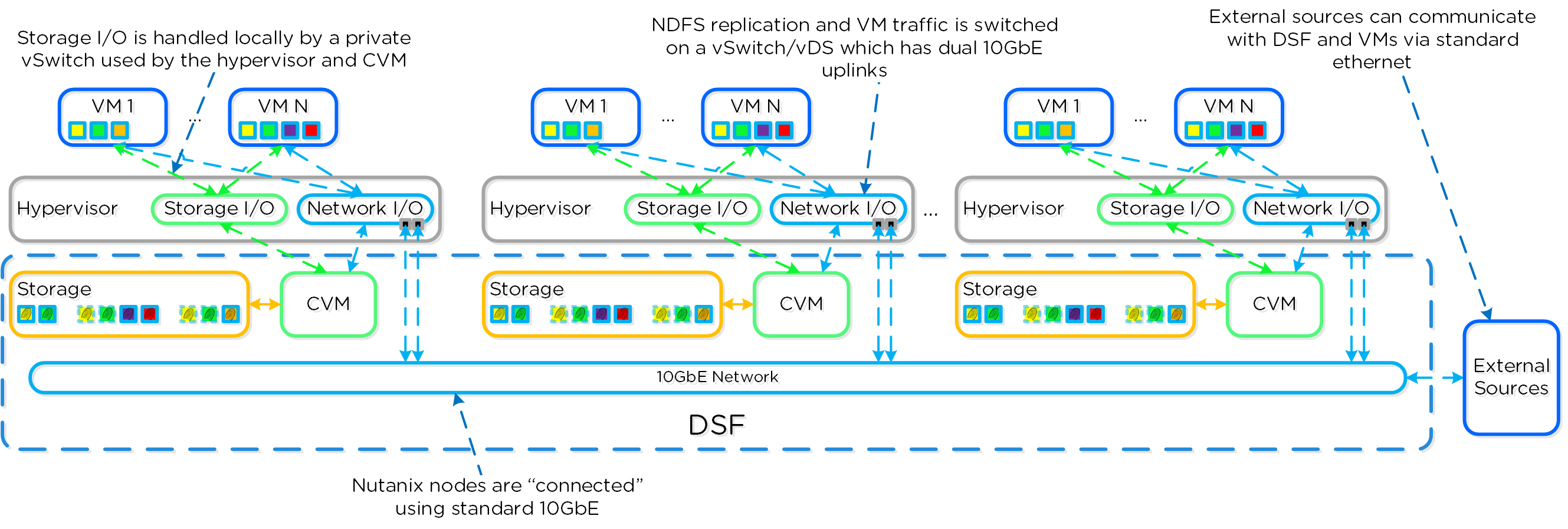
As discussed in the VMware vSAN article linked above, the storage I/O latency introduced by the network when a VM is not local to it’s data is negligible when compared to flash device latencies. Therefore the impact of running a VM away from it’s data should be transparent to the VM end user(s).
Conclusion and Wrap Up
So there we have it. Two posts (find part 1 here) with lots of concepts to understand. I think I’ve covered the “big hitters” although it’s possible missed the odd one… I don’t think so!
And that’s just intra-cluster storage and data protection. We have not looked at cross cluster replication and data protection (akin to VMware SRM) yet! Perhaps in a later post. ![]()
Hopefully you found these posts valuable, especially for the VMware vSAN admin looking at Nutanix DSF for the first time.
Again, if you are still thirsty for more take a look at the Book of AOS from the Nutanix Bible.
-Chris

