


When deploying NSX there certain are points during deployment that lend themselves to spending a couple of extra minutes to double checking configuration and connectivity before moving on to the next deployment step.
A couple of quick minutes here and there can save hours of troubleshooting later on.
Overview
What to Test and When
Typically during a deployment, there are three stages where a quick ping test comes handy prior to moving on with the NSX deployment. These are:
-
Host TEP Connectivity - Typically just after the ESXi hosts have prepared for NSX - Confirm host TEPs can ping the gateway on the physical network with a recommended MTU of >=1700 bytes.
-
Edge TEP Connectivity - Typically just after the edge nodes have been deployed - Confirm edge TEPs can ping the gateway on the physical network with a recommended MTU of >=1700 bytes.
-
Tier-0 Uplink Connectivity - Once the Tier-0 has been configured with a External (uplink) interface(s). These interfaces carry North/South traffic out/in to the NSX environment. Recommended MTU for these is 1500 bytes.
All three networks need to be routable.
NSX Gateway Components
Before we get into the testing we need to appreciate the make up of an NSX gateway:
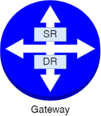
A gateway can be either a Tier-0 or a Tier-1 gateway, depending on the design requirements:
- A Tier-0 gateway provides north-south connectivity. In a single-tier topology, the Tier-0 gateway also provides east-west connectivity.
- A Tier-1 gateway provides east-west connectivity.
A Tier-1 and a Tier-0 gateway can have Distributed Router (DR) and Service Router (SR) components.
A Distributed Router (DR) has the following features:
- Provides basic packet-forwarding functionalities
- Spans all transport nodes (host and edge transport nodes)
- Runs as a kernel module in the ESXi hypervisor
- Provides distributed routing functionality
- Provides first-hop routing for workloads
A Service Router (SR) has the following features:
- Provides north-south routing
- Provides centralized services such as NAT and load balancing
- Required for the uplinks to external networks
- Deployed in edge transport nodes
A Distributed Router is always created when creating a gateway.
A Service Router is automatically created on the edge node when you configure the gateway with an edge cluster.
Maximum Transmission Unit (MTU)
OK, with DRs and SRs understood, we need to briefly talk about MTU. Given that our NSX Tunnel Endpoints (TEPs) encapsulate our standard 1500 byte MTU packets using the Geneve protocol, we need to ensure that our overlay networks are able to handle packets larger than 1500 bytes without fragmenting the packet.
The VMware NSX Reference Design Guide v3.2 (pdf). Page 236 onwards covers our situation (emphasis mine):
A minimum required MTU is 1600. However, MTU of 1700 bytes is recommended to address the whole possibility of a variety of functions and future proof the environment for an expanding Geneve header.
So we also need to test MTU with our ping testing.
Host TEP Connectivity
From the GUI, these are the interfaces we are interested in:
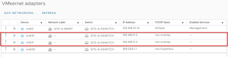
OK, let’s SSH to our first ESXi host and list it’s VMKernel network interfaces:
esxcfg-vmknic -lFrom the below we can see that our host has two NSX VMKernel interfaces (denoted by them being on the vxlan NetStack (last column):
[root@esxi-site-a-1:~] esxcfg-vmknic -l
Interface  Port Group/DVPort/Opaque Network        IP Family IP Address     Netmask         Broadcast       MAC Address       MTU     TSO MSS   Enabled Type    NetStack
vmk0       10                                      IPv4      192.168.10.10  255.255.255.0   192.168.10.255  00:50:56:bb:37:15 1500    65535     true    STATIC  defaultTcpipStack
vmk10      ad451e93-a608-48ac-8099-84fbb44f3a23    IPv4      192.168.11.2   255.255.255.0   192.168.11.255  00:50:56:63:77:7b 1700    65535     true    STATIC  vxlan
vmk11      83159744-e019-47d5-bf0c-116c1d723968    IPv4      192.168.11.3   255.255.255.0   192.168.11.255  00:50:56:65:bc:07 1700    65535     true    STATIC  vxlan
vmk50      60c5dbc7-0cd0-43e0-bd17-6cfdb14d6e04    IPv4      169.254.1.1    255.255.0.0     169.254.255.255 00:50:56:60:7f:18 1700    65535     true    STATIC  hyperbus
They also have an MTU configured of 1700 (eighth column).
Lets construct our command to ping the host TEP physical network gateway and check for an MTU of 1700. (See VMware KB 1003728 for syntax).
The command looks like this:
vmkping ++netstack=vxlan <GATEWAY_IP> -d -s 1672 -c 5[root@esxi-site-a-1:~] vmkping ++netstack=vxlan 192.168.11.1 -d -s 1672 -c 5
PING 192.168.11.1 (192.168.11.1): 1672 data bytes
1680 bytes from 192.168.11.1: icmp_seq=0 ttl=64 time=0.417 ms
1680 bytes from 192.168.11.1: icmp_seq=1 ttl=64 time=0.617 ms
1680 bytes from 192.168.11.1: icmp_seq=2 ttl=64 time=0.685 ms
1680 bytes from 192.168.11.1: icmp_seq=3 ttl=64 time=0.658 ms
1680 bytes from 192.168.11.1: icmp_seq=4 ttl=64 time=0.637 ms
--- 192.168.11.1 ping statistics ---
5 packets transmitted, 5 packets received, 0% packet loss
round-trip min/avg/max = 0.417/0.603/0.685 ms
[root@esxi-site-a-1:~]Nice. That is working perfectly.
Edge TEP Connectivity
From the GUI, these are the interfaces we are interested in:
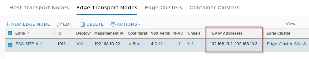
Given that our edges can span tier-0 and tier-1 gateways and that each of those gateways can have DR and SR components each doing their own job, we need to ensure that not only are we using the correct gateway but the correct router too.
Let’s SSH to our first edge and take a look using the following command:
get logical-routeresg-site-a-1> get logical-router
Wed Feb 08 2023 UTC 19:50:57.747
Logical Router
UUID VRF LR-ID Name Type Ports Neighbors
736a80e3-23f6-5a2d-81d6-bbefb2786666 0 0 TUNNEL 4 2/5000
f08525af-e5b5-4bce-9d8f-144ffcee1b7a 1 2 SR-Tier-0-Site-A SERVICE_ROUTER_TIER0 6 1/50000
16a7a4f9-57e1-48ab-9699-71e7e692da2e 3 1 DR-Tier-0-Site-A DISTRIBUTED_ROUTER_TIER0 5 2/50000
83061617-17e6-4d89-ba5f-9fcf435f3eb4 4 6 SR-Tier-1-Site-A SERVICE_ROUTER_TIER1 5 2/50000
79f4951c-87ce-4268-9a9c-29d10e5756ad 5 5 DR-Tier-1-Site-A DISTRIBUTED_ROUTER_TIER1 6 0/50000As you can see, I have SRs and DRs for my Site-A Tier-0 and Tier-1 gateways configured.
When testing Edge TEP connectivity, we are interested in the TUNNEL router as that deals with our TEP traffic.
Using the TUNNEL router UUID, let’s take a look at it’s forwarding table:
get logical-router <ROUTER_UUID> forwardingesg-site-a-1> get logical-router 736a80e3-23f6-5a2d-81d6-bbefb2786666 forwarding
Wed Feb 08 2023 UTC 19:51:03.086
Logical Router
UUID VRF LR-ID Name Type
736a80e3-23f6-5a2d-81d6-bbefb2786666 0 0 TUNNEL
IPv4 Forwarding Table
IP Prefix Gateway IP Type UUID Gateway MAC
0.0.0.0/0 192.168.13.1 route c7a99c20-9a00-5d9e-ac45-112e6a787435 00:50:56:bb:ff:b1
192.168.13.1 b7e1a1c3-4203-5368-9a80-a639419267da 00:50:56:bb:ff:b1
192.168.13.0/24 route c7a99c20-9a00-5d9e-ac45-112e6a787435
b7e1a1c3-4203-5368-9a80-a639419267da
192.168.13.2/32 route 8f6a05bd-e029-5be4-ac5f-d5a9f5823ca0
192.168.13.3/32 route 8f6a05bd-e029-5be4-ac5f-d5a9f5823ca0Yep we can see that the tunnel router is using our configured Edge TEP gateway of 192.168.13.1.
Lets construct our command to ping the host TEP physical network gateway and check for an MTU of 1700. (See NSX-T Command-Line Interface Reference for syntax).
ping <GATEWAY_IP> source <EDGE_TEP_IP> vrfid <TUNNEL_VRF_ID> size 1672 dfbit enable repeat 5 Which when run:
esg-site-a-1> ping 192.168.13.1 source 192.168.13.2 vrfid 0 size 1672 dfbit enable repeat 5
PING 192.168.13.1 (192.168.13.1) from 192.168.13.2: 1672 data bytes
1680 bytes from 192.168.13.1: icmp_seq=0 ttl=64 time=2.105 ms
1680 bytes from 192.168.13.1: icmp_seq=1 ttl=64 time=2.340 ms
1680 bytes from 192.168.13.1: icmp_seq=2 ttl=64 time=2.677 ms
1680 bytes from 192.168.13.1: icmp_seq=3 ttl=64 time=2.016 ms
1680 bytes from 192.168.13.1: icmp_seq=4 ttl=64 time=2.121 ms

--- 192.168.13.1 ping statistics ---
5 packets transmitted, 5 packets received, 0.0% packet loss
round-trip min/avg/max/stddev = 2.016/2.252/2.677/0.238 ms

esg-site-a-1>
Nice. That is also working perfectly.
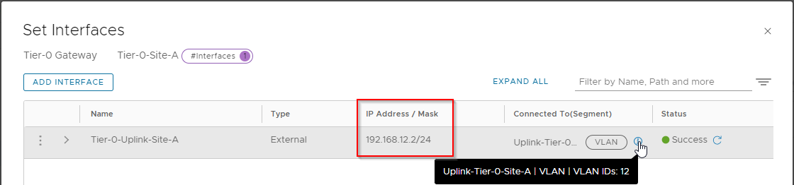
Tier-0 Uplink Connectivity
Finally, lets check North bound connectivity out of the NSX environment to the gateway out on the physical network.
From the GUI (Tier-0 > Interfaces > External and Service Interfaces), these are the interfaces we are interested in:
Again, we can check that from our edges. Let’s remind ourselves of the logical routers present on our edge:
get logical-routeresg-site-a-1> get logical-router
Wed Feb 08 2023 UTC 19:50:57.747
Logical Router
UUID VRF LR-ID Name Type Ports Neighbors
736a80e3-23f6-5a2d-81d6-bbefb2786666 0 0 TUNNEL 4 2/5000
f08525af-e5b5-4bce-9d8f-144ffcee1b7a 1 2 SR-Tier-0-Site-A SERVICE_ROUTER_TIER0 6 1/50000
16a7a4f9-57e1-48ab-9699-71e7e692da2e 3 1 DR-Tier-0-Site-A DISTRIBUTED_ROUTER_TIER0 5 2/50000
83061617-17e6-4d89-ba5f-9fcf435f3eb4 4 6 SR-Tier-1-Site-A SERVICE_ROUTER_TIER1 5 2/50000
79f4951c-87ce-4268-9a9c-29d10e5756ad 5 5 DR-Tier-1-Site-A DISTRIBUTED_ROUTER_TIER1 6 0/50000As we are talking North/South traffic we need to be using the Service Router context of our Tier-0 router. In the case above, that’s VRF ID 1.
A reminder of the command, remember we are not so much worried about the larger MTU value here, 1500 is fine. (Again, see NSX-T Command-Line Interface Reference for syntax):
ping <GATEWAY_IP> source <EDGE_TEP_IP> vrfid <SR-Tier-0_VRF_ID> size 1472 dfbit enable repeat 5 esg-site-a-1> ping 192.168.12.1 source 192.168.12.2 vrfid 1 size 1472 dfbit enable repeat 5
PING 192.168.12.1 (192.168.12.1) from 192.168.12.2: 1472 data bytes
1480 bytes from 192.168.12.1: icmp_seq=0 ttl=64 time=2.343 ms
1480 bytes from 192.168.12.1: icmp_seq=1 ttl=64 time=1.894 ms
1480 bytes from 192.168.12.1: icmp_seq=2 ttl=64 time=1.528 ms
1480 bytes from 192.168.12.1: icmp_seq=3 ttl=64 time=1.320 ms
1480 bytes from 192.168.12.1: icmp_seq=4 ttl=64 time=2.691 ms
--- 192.168.12.1 ping statistics ---
5 packets transmitted, 5 packets received, 0.0% packet loss
round-trip min/avg/max/stddev = 1.320/1.955/2.691/0.506 ms
esg-site-a-1>Conclusion and Wrap Up
As Sean Connery once said:
 |
 |
 |
Yes I’m old. Referencing a 33 year old movie at this point (2023) is …yeah… For those that have missed out or simply just forgotten: One Ping Only - YouTube.
Not quite as badass as Sean Connery (RIP) or Sam Neill, using five pings instead of one ping only, but hey I’m OK with that!
-Chris